Español
 عربى
 русский
Content
- 1 Introduction
- 2 Product Overview
- 3 Design Advantages Over Basic Surface Boxes
- 4 Electrical Performance and Signal Integrity
- 5 Mechanical Reliability and Service Life
- 6 Manufacturing Capabilities and Quality Strengths
- 7 Environmental Resistance and Compliance
- 8 Standards and System Compatibility
- 9 Applications
- 10 Packaging, Storage, and Supply
- 11 Customization and OEM or ODM Support
- 12 Why Manufacturing Experience Matters to Buyers
- 13 Comparison with Competing Product Types
- 14 Inspection and Acceptance Checklist
- 15 Q&A
- 15.1 What is the SMT-4402-2PC6-FTP used for?
- 15.2 Can the surface box be installed on a wall and a desktop?
- 15.3 Does the product support both T568A and T568B?
- 15.4 What cable gauge can be terminated in the IDC terminal?
- 15.5 Is this an unshielded or shielded surface box?
- 15.6 What is the operating temperature range?
- 15.7 How durable is the RJ45 connection?
- 15.8 What materials are used in the product?
- 15.9 Does the product meet RoHS requirements?
- 15.10 Can the packaging be customized?
- 15.11 Is the product suitable for every CAT6 network?
- 15.12 What should be checked before installation?
- 16 Conclusion
- 17 References
- 18 Product: SMT-4402-2PC6-FTP CAT6 Shielded 90 Degree Surface Box
Introduction
Reliable network infrastructure depends on more than cable quality alone. Every transition point between horizontal cabling, equipment cords, and user devices must preserve signal integrity, provide mechanical protection, and support efficient installation. The SMT-4402-2PC6-FTP CAT6 Shielded 90-Degree Surface Box is designed for this purpose. It provides a compact termination and connection point for structured cabling systems in offices, commercial buildings, communication rooms, smart homes, educational facilities, and other work areas where a wall-mounted or desktop outlet is required.
As a shielded surface-mount box, this product combines an RJ45 connection interface with an IDC termination system. Its 90-degree surface-box format is intended to make cable routing more convenient where space is limited or where installers need the connection to sit neatly against a wall or desktop. The product supports T568A and T568B wiring sequences and is compatible with Krone tool IDC termination methods.
The unit is manufactured from phosphor bronze, nickel-plated and gold-plated contact materials, PC polycarbonate plastic, and FR4 printed circuit board material. These materials are selected to provide stable electrical contact, mechanical durability, and resistance to common environmental stresses. The product is also designed to meet RoHS environmental requirements and is manufactured according to applicable telecommunications wiring specifications identified in the supplied technical documentation.
This article examines the product’s design, installation value, technical characteristics, manufacturing strengths, quality-control advantages, application range, and purchasing considerations. It also explains how the product can compare favorably with ordinary unshielded or less adaptable surface boxes when a project requires reliable termination, compact installation, and repeatable performance.
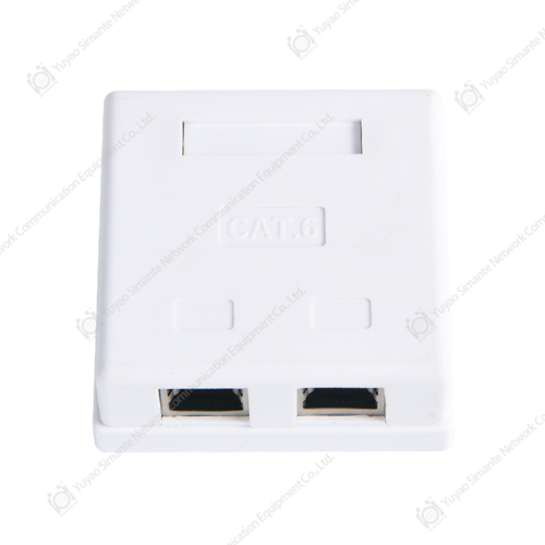
SMT-4402-2PC6-FTP CAT6 Shielded 90 Degree Surface Box
Product Overview
The SMT-4402-2PC6-FTP is a shielded CAT6 90-degree surface box categorized as a surface-mount box for copper structured cabling systems. It is intended to connect horizontal wiring with work-area wiring on the same building floor. In practical terms, it can serve as the termination point between a permanent link running through a wall, ceiling, floor, or cable pathway and the patch cord connected to a computer, telephone, access point, camera, control device, or other network terminal.
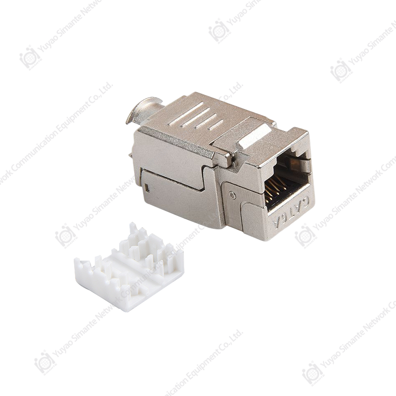
The product design includes an RJ45 jack with a jumper and an IDC termination area for horizontal wiring. This arrangement allows the installer to terminate the incoming twisted-pair cable at the back or internal portion of the box while leaving the front RJ45 interface accessible to the user. The result is a cleaner connection point than a loose cable junction and a more organized alternative to exposed cable terminations.
The 90-degree design is especially useful in installations where the cable needs to approach the outlet horizontally or vertically without creating an excessively sharp bend. It can help guide the cable into the connection point while keeping the overall assembly close to the mounting surface. This is useful behind desks, beside workstations, in cabinets, and along walls where a conventional straight outlet may require more clearance.
The product can be installed on a wall or used on a desktop. This flexibility allows the same basic product platform to serve multiple project environments. Installers can use it as a permanent surface outlet in a renovated office where recessed wall boxes are unavailable, or as a desktop connection point where drilling and embedded installation are undesirable.
Main Product Characteristics
| Item | Specification or Feature |
|---|---|
| Product type | CAT6 shielded 90-degree surface box |
| Category | Surface Mount Box |
| Connection interface | RJ45 jack with jumper and IDC termination |
| Wiring sequence | T568A and T568B |
| IDC termination | Krone tool compatible; suitable for 22–26 AWG twisted pair |
| Mounting options | Wall or desktop installation |
| Frequency range | 1–250 MHz |
| Working voltage | 125 V |
| Withstand voltage | DC 1000 V or AC 750 V for one minute without breakdown or arcing |
| Contact materials | Phosphor bronze with gold or nickel plating as specified |
| Housing material | PC polycarbonate |
| PCB material | FR4 |
| Environmental compliance | RoHS requirements |
| Operating temperature | -25°C to +70°C |
| Recommended humidity condition | Not more than 85 percent under the stated test condition |
Design Advantages Over Basic Surface Boxes
One of the primary advantages of this model is the combination of shielded construction and a practical surface-mount format. Many basic surface boxes are designed primarily for low-cost installation and may not provide the same level of protection against electromagnetic interference. A shielded FTP-oriented product can be more appropriate in environments where network cables run near power circuits, motors, lighting systems, industrial equipment, or other potential interference sources.
Shielding does not eliminate every possible source of network interference, and the complete cabling system must be correctly bonded and installed to obtain the intended benefit. However, when the cable, patch panel, connectors, and grounding arrangements are selected consistently, a shielded surface box can contribute to better control of unwanted electromagnetic coupling. This is a valuable consideration for commercial, industrial, laboratory, security, and automation applications.
The 90-degree shape is another practical advantage. A straight surface box can force a cable to project directly outward or bend sharply near the termination point. Excessive bending can place stress on the cable jacket, conductors, plug, or outlet. The angled format gives installers a more controlled cable path and can reduce the space needed between the outlet and nearby furniture or equipment.
The product also supports both wall and desktop use. Competitors that provide only one mounting method may require separate models for different installation environments. A versatile surface box can simplify project planning, reduce the number of product types held in stock, and help contractors respond to changes in site conditions.
Another advantage is the use of IDC termination. IDC systems are widely accepted in structured cabling because they allow insulated conductors to be terminated without removing the insulation from each individual wire. The Krone tool method is familiar to many network installers and supports fast, repeatable terminations. The specified 22–26 AWG range covers many commonly used twisted-pair cables, although the exact cable construction should always be checked before installation.
The unit is also designed for repeated service. The stated durability values include up to 750 insertion and removal cycles for the plug and socket and up to 250 wire termination operations. These values are important for maintenance teams and environments where the outlet may be serviced, reconfigured, or tested multiple times during its working life.
Compact Installation and Cable Management
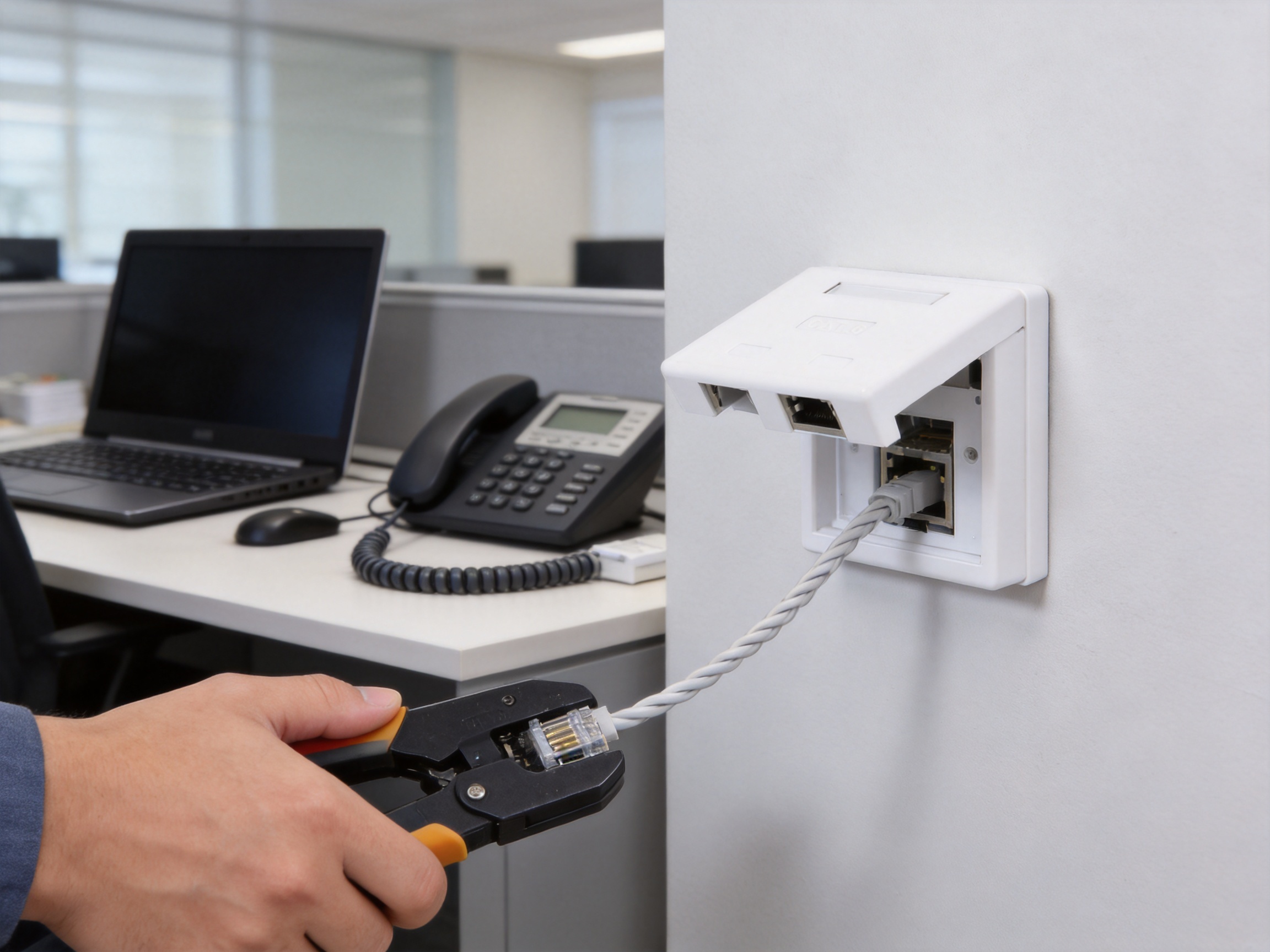
Surface-mounted outlets are often selected when a building cannot accommodate a recessed electrical or communications box. They are also useful during renovation work, temporary installations, and retrofit projects. The SMT-4402-2PC6-FTP can be mounted directly onto a suitable wall or positioned on a desktop, allowing network access to be added without extensive construction work.
The enclosure helps organize the cable transition and keeps the IDC termination protected from accidental contact. This is particularly important in work areas where cables may be moved, cleaned, or exposed to vibration. A properly secured surface box is easier to identify, test, and replace than an unprotected cable joint.
For desktop installations, the product may be positioned near a computer, IP phone, printer, wireless access point, or other device. For wall installations, it can be placed at a convenient workstation height or in a service area. The final mounting method should account for cable bend radius, strain relief, access for testing, and separation from high-voltage wiring.
Electrical Performance and Signal Integrity
The supplied documentation identifies a frequency range of 1 to 250 MHz. This operating range is relevant to high-speed copper data transmission and supports the use of the product in structured cabling applications requiring stable performance across a broad signal spectrum. The actual channel performance will depend on the complete link, including cable type, patch cords, connectors, installation quality, grounding, cable length, and external interference.
The product has a stated working voltage of 125 V and a dielectric withstand rating of DC 1000 V or AC 750 V for one minute without breakdown or arcing under the specified test conditions. These values indicate the insulation system’s ability to withstand a controlled electrical stress test. They should not be interpreted as permission to connect the surface box to mains power or use it outside its intended telecommunications application.
The specified initial insulation resistance is at least 100 MΩ. The documentation also states that the insulation resistance remains at least 100 MΩ after the constant damp-heat test. High insulation resistance helps limit unwanted leakage current between conductive elements and supports consistent electrical separation inside the connector assembly.
The stated near-end crosstalk attenuation, or NEXT, is at least 2.5 dB according to the provided technical information. Crosstalk is caused when a signal in one twisted pair couples into an adjacent pair. Connector geometry, pair separation, contact layout, cable construction, and termination quality can all influence this characteristic. For a complete network design, installers and engineers should evaluate the entire permanent link or channel rather than relying on one component specification alone.
The product supports both T568A and T568B line sequences. This gives installers flexibility when matching an existing cabling system. However, all terminations within a link should follow a consistent and documented wiring scheme unless a specific crossover arrangement is intentionally required. Inconsistent pin assignments can cause incorrect pair mapping, reduced performance, or complete loss of connectivity.
Contact Materials and Surface Plating
The contact system uses phosphor bronze for the gold-plated contact pins. Phosphor bronze is commonly selected for connector contacts because it provides a useful balance of conductivity, spring performance, mechanical strength, and resistance to fatigue. The spring properties of the contact help maintain pressure against the mating plug during repeated insertion and removal.
The IDC card wire terminal is specified as phosphor bronze with nickel plating. Nickel plating provides a durable protective surface and helps resist corrosion during normal use. The contact interface is further specified with a gold-plated layer ranging from 6 to 50 microinches, according to the supplied product information. Gold is valued in connector applications because it resists oxidation and can maintain a reliable low-level signal interface when properly applied.
Plating thickness and plating quality are only part of connector reliability. The base material, contact geometry, plating adhesion, stamping accuracy, assembly pressure, and cleanliness of the finished contact all matter. A controlled manufacturing process is therefore essential to ensure that the material specification is reflected in the finished product.
Mechanical Reliability and Service Life
A communications outlet must withstand more than normal electrical operation. It may be handled by installers, connected and disconnected by users, exposed to cable movement, and subjected to occasional pulling or impact. The product documentation specifies an insertion force of no more than 20 N and a pull-out force of no less than 20 N. These values describe the effort associated with mating and unmating and the connector’s resistance to unintended separation.
The connector connection device is also specified to withstand a 50 N force for 60 ±5 seconds. This type of mechanical test evaluates the ability of the assembled connection to resist a controlled load without unacceptable displacement or failure. Such performance is useful in installations where a patch cord may be moved or where the outlet is located near a busy work area.
IDC termination is specified for 22–26 AWG twisted-pair cable. Installers should select a cable within this range and use the correct termination tool. The conductors should be fully seated in the IDC slots, and excess wire should be trimmed cleanly. Poor termination technique can create high resistance, intermittent operation, pair imbalance, or damage to the terminal.
The stated durability of 750 plug-and-socket insertion cycles is suitable for many office and commercial environments. The 250 termination-cycle specification is also valuable for service providers and OEM users who may reconfigure or customize products during installation. Nevertheless, repeated retermination should be performed carefully, because every IDC operation can affect the conductor and terminal interface.
Housing and Structural Materials
The housing uses PC polycarbonate. Polycarbonate is known for its impact resistance, dimensional stability, and ability to perform across a broad temperature range. It is commonly used in communication accessories where a light but durable enclosure is needed. The housing also helps protect internal contacts and the PCB from accidental contact and ordinary handling.
The PCB is made from FR4 material. FR4 is a glass-fiber-reinforced epoxy laminate widely used for printed circuit boards because it provides mechanical support, electrical insulation, and stable dimensional properties. In a compact connector assembly, the PCB helps maintain the designed relationship between contact points and wiring elements.
Material selection must be combined with accurate molding, stamping, plating, assembly, and inspection. Even a high-quality raw material cannot compensate for poor dimensional control or inadequate process management. This is why the production system behind the product is a significant consideration for buyers.
Manufacturing Capabilities and Quality Strengths
Yuyao Simante Network Communication Equipment Co., Ltd. is a professional manufacturer of network cabling solutions and optical fiber products. Its activities include product design, development, sales, and service. The company’s experience in network connectivity products supports the production of surface boxes, keystone jacks, patch panels, wall face plates, data sockets, and related components.
The company reports nearly 20 years of service in the network cabling field. This length of operating experience can provide practical knowledge of connector design, installation requirements, customer specifications, and international market expectations. Product development based on accumulated field experience can help manufacturers identify recurring installation problems and improve future product generations.
The company has more than 10 engineers and more than 30 full-time technical personnel. An engineering and technical team of this kind can contribute to design verification, tooling improvement, process documentation, production troubleshooting, and customer-specific development. Technical support is especially important for OEM and ODM projects where the buyer may require changes to packaging, labeling, color, structure, electrical performance, or mounting arrangements.
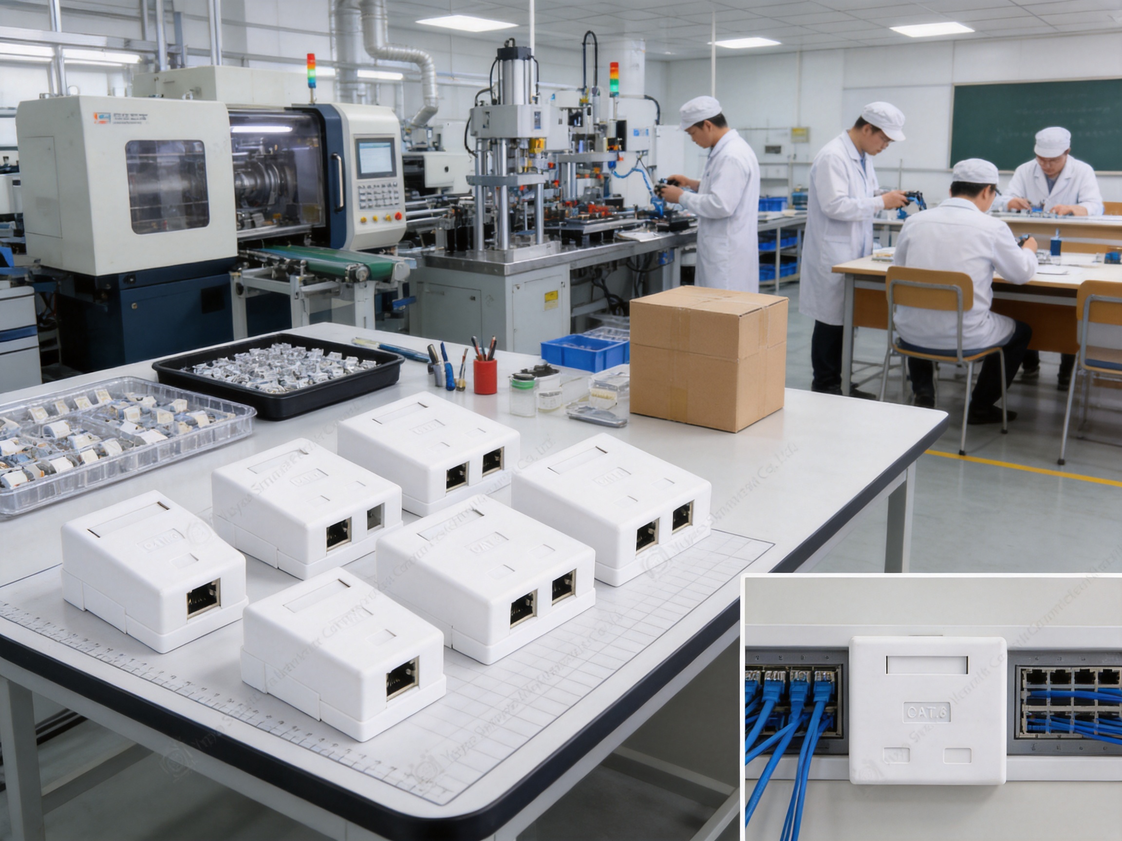
The factory has 10 regular and customization production lines, 10 fully automatic injection molding machines, 20 semi-automatic injection molding machines, and eight types of automatic installation machines, according to the supplied company information. These resources indicate a manufacturing structure capable of supporting both standard products and customized orders.
Injection molding capacity is important for products using polycarbonate housings. Automated or semi-automated molding equipment can support stable production volumes, consistent dimensions, and repeatable housing quality when properly managed. It can also help reduce variation between batches and improve the fit between the enclosure, PCB, contact assembly, and mounting features.
Automatic installation equipment can improve assembly consistency. Connector products contain small parts that must be placed with controlled force and precise positioning. Automation may reduce manual variation, increase throughput, and support process monitoring. However, automation is most effective when supported by inspection systems, preventive maintenance, calibrated tooling, and trained production personnel.
The manufacturer reports an annual output of more than nine million units. This production scale can benefit distributors and project contractors that need consistent supply over repeated orders. It may also support better production scheduling, component purchasing, and inventory planning. For large projects, supply continuity can be as important as individual product performance.
Process Control from Design to Finished Product
A reliable connector begins with design control. The housing, contact pins, IDC terminals, PCB, shielding elements, and mounting features must be designed as one coordinated assembly. The company’s engineering resources can support the evaluation of contact spacing, cable entry direction, wiring labels, plug retention, and mechanical clearances before mass production begins.
Tooling quality is another important factor. Molds used for polycarbonate housings must maintain accurate dimensions and consistent cavity filling. Stamping tools for phosphor bronze contacts must produce clean edges and repeatable contact geometry. Plating processes must provide the required surface coverage and thickness. Each of these stages can influence electrical and mechanical performance.
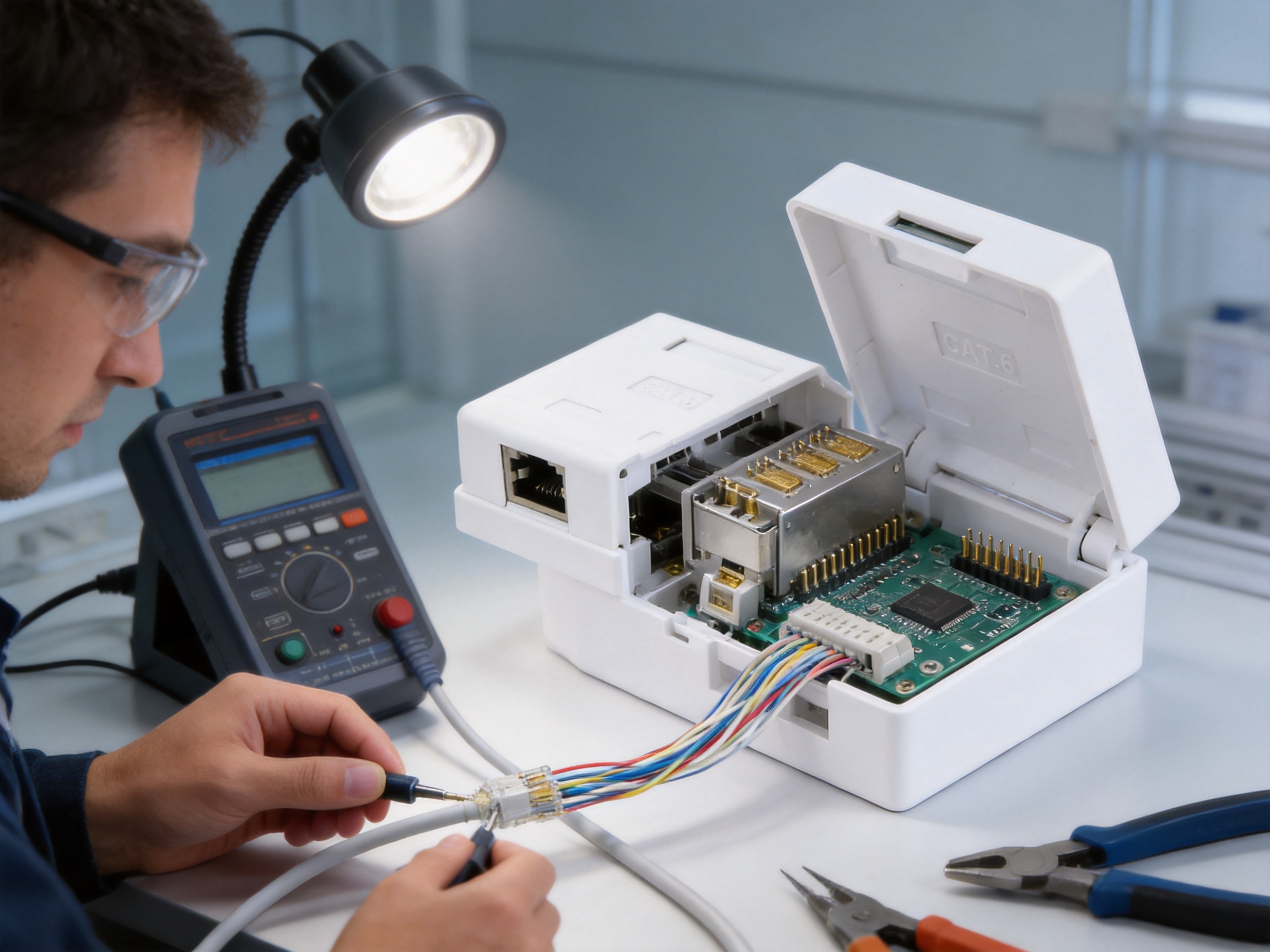
Assembly controls are necessary to ensure that the contact system, PCB, housing, and IDC terminals are correctly positioned. Incorrect assembly can produce loose contacts, poor plug retention, wiring errors, or damage to the shielding path. A structured production process should include work instructions, sampling inspections, traceability, and final verification.
Testing is also part of the company’s stated quality approach. The company indicates that it meets comprehensive customer testing requirements through performance testing. For this type of product, suitable evaluations may include contact continuity, wire-map verification, insulation resistance, dielectric withstand, insertion and withdrawal force, plug retention, IDC termination integrity, dimensional inspection, and environmental testing.
Environmental Resistance and Compliance
The product is specified for a temperature range of -25°C to +70°C. This range covers many indoor commercial and industrial installation environments. The product information also identifies humidity performance of no more than 85 percent under the stated condition involving a temperature of 85°C ±3°C. Buyers should review the detailed test method and distinguish between an operating condition and a laboratory test condition before applying the product in an unusual environment.
Humidity can affect connector performance by encouraging corrosion, reducing insulation resistance, and causing contamination on contact surfaces. The use of plated phosphor bronze contacts, a protective housing, and suitable assembly practices helps address these risks. Installation in areas with condensation, direct water exposure, chemical vapor, or outdoor weather requires additional enclosure and environmental protection measures.
The product documentation includes a salt-spray test procedure. The specified salt solution has a pH value between 6.5 and 7.2 before atomization, a sodium chloride concentration of 5 ±0.1 percent by mass, and a recommended continuous atomization duration of 48 hours. The test conditions also require protection from oil, dust, and other impurities that could affect the result.
Salt-spray testing is an accelerated corrosion evaluation. It does not reproduce every real-world environment, but it can help assess the resistance of plated metal surfaces under controlled conditions. This is particularly relevant for products that may be shipped, stored, or installed in coastal regions or locations with elevated atmospheric contamination.
The product is identified as meeting RoHS environmental protection requirements. RoHS compliance helps address restrictions on specified hazardous substances in electrical and electronic products. For projects with formal compliance requirements, purchasers should request current compliance documentation, declarations, or test reports applicable to the exact product version and production batch.
Standards and System Compatibility
The supplied information identifies YD/T 926.1-2009 as a general specification and YD/T 926.3-2009 as a sub-standard. These telecommunications standards provide a reference framework for the product’s design and application. The stated design grade is universal connector grade 2.
The product is intended to be used with connectors from the same standard series or with components that are technically compatible. Compatibility should not be assumed solely from the appearance of an RJ45 interface. The cable category, shielding design, conductor gauge, contact arrangement, termination method, and performance requirements must all be considered.
The product title identifies the unit as CAT6 shielded. The supplied series description also refers to Category 5E transmission standards. Because these descriptions are not completely identical, project engineers should confirm the required category rating, test documentation, and intended system performance before placing a large order. A component used in a CAT6 channel should be evaluated as part of the complete CAT6 permanent link or channel.
Correct system matching is essential. A shielded outlet should be paired with compatible shielded cable and suitable shielded patch cords when shielding performance is required. The grounding and bonding design must follow applicable local electrical and telecommunications practices. If only one part of the system is shielded, the overall shielding benefit may be limited.
Installation Recommendations
Before installation, inspect the cable jacket, confirm the cable type and conductor gauge, identify the selected wiring sequence, and verify that the mounting surface is clean and stable. The cable should be routed without excessive tension, crushing, twisting, or bending. Sufficient service loop should be retained where the installation design allows it.
Choose either T568A or T568B according to the project specification. Place each conductor in the correct IDC slot and use a compatible Krone termination tool. The conductors should be seated fully and trimmed as required. Avoid unnecessary untwisting of the pairs, because maintaining pair geometry near the termination helps preserve transmission performance.
After termination, verify the wire map with an appropriate cable tester. Testing should identify open circuits, short circuits, reversed pairs, split pairs, and incorrect sequence. For higher-performance installations, certification testing may be used to evaluate insertion loss, return loss, NEXT, far-end crosstalk, propagation delay, and other channel parameters.
Secure the surface box so that cable movement does not transfer force directly to the IDC area or RJ45 jack. Confirm that the cover and housing are correctly assembled. Where the product is used as part of a shielded system, verify continuity of the shield path and the connection to the designated grounding or bonding infrastructure.
Applications
The SMT-4402-2PC6-FTP can be used in offices where workstations require a neat connection point without installing recessed wall outlets. It can support desktop computers, IP telephones, printers, network storage devices, conference-room equipment, and other Ethernet-enabled terminals.
In educational environments, surface-mounted outlets can provide network connections in classrooms, laboratories, libraries, and training rooms. The ability to mount the box on a wall or desktop can simplify upgrades in older buildings where concealed cabling routes are limited.
Commercial facilities may use the product in retail counters, reception desks, meeting rooms, hotels, and service areas. Its compact shape can help maintain a more organized appearance while protecting the termination from casual contact.
Industrial and automation environments may benefit from shielded construction where communications cabling is routed near motors, drives, control cabinets, or other equipment that can create electromagnetic noise. In such applications, the complete cable system must be designed with appropriate separation, grounding, and environmental protection.
The product may also be used in smart-home installations, security systems, building automation, and communication equipment. Applications involving surveillance cameras, wireless access points, access-control devices, and sensors can use surface outlets when a convenient local connection point is needed.
Packaging, Storage, and Supply
The product is packaged in a special blister bag and then placed in a cardboard box. Product accessories are placed with the unit, and a label identifying the model and quantity is affixed to the upper-left area of the carton front according to the supplied packaging description.
The standard packing quantity is stated as 10 boxes per carton, 20 units per box, and 200 units per carton. Buyers should confirm the final packing configuration before shipment because packaging may be adjusted for customer-specific requirements, export regulations, or private-label programs.
Packaged products should be stored in a warehouse with an ambient temperature of -5°C to +30°C and relative humidity not exceeding 70 percent. The storage area should be free from acid, alkali, and other corrosive gases. The stated storage period is three years under the specified conditions.
Correct storage is important even for a robust connector. Excessive humidity, dust, corrosive vapors, direct sunlight, or mechanical compression can affect plastic parts, metal plating, labels, and packaging integrity. Products should remain in their original packaging until they are ready for installation.
Customization and OEM or ODM Support
Projects often require more than a standard catalog item. Contractors, distributors, and system brands may need custom packaging, customer-specified labels, modified colors, special quantities, or documentation in a particular format. The product information identifies customer-specified packaging as an available product-use option.
OEM and ODM cooperation can extend to product appearance, branding, assembly configuration, cable-entry direction, mounting accessories, and inspection requirements. A manufacturer with engineering staff, molding equipment, installation machinery, and multiple production lines is better positioned to evaluate such requests than a trading company without direct production control.
Customization should be managed through a formal technical specification. The document should identify the exact product code, materials, plating requirements, wiring sequence, packaging, labels, operating environment, test standards, acceptance criteria, and revision level. This reduces the risk that a customized order will be manufactured differently from the buyer’s expectations.
For recurring projects, buyers may also request pre-production samples, first-article approval, inspection reports, packing photographs, and batch traceability. These controls can improve consistency across repeat orders and support quality documentation for the final network installation.
Why Manufacturing Experience Matters to Buyers
Purchasing a network accessory is not only a matter of comparing the lowest unit price. A surface box affects installation labor, troubleshooting time, network reliability, and future maintenance. A product with accurate dimensions and consistent termination characteristics can reduce installation errors and help contractors complete projects more efficiently.
Manufacturing experience also contributes to supply reliability. Stable production lines and established component sourcing can reduce the risk of unexpected delays. This is valuable for projects with fixed completion dates, especially when many outlets must be installed across multiple floors or buildings.
Technical support is another differentiating factor. When a project involves shielding, unusual cable types, custom packaging, or system testing, buyers may need assistance before ordering. A manufacturer that understands structured cabling can provide more useful information about compatibility, installation, and product selection.
The company’s reported export activity in Europe, Australia, Africa, the Middle East, and Southeast Asia indicates experience serving customers with different market requirements. Export experience may include documentation, packaging, product labeling, inspection procedures, and communication across different technical and commercial environments.
Although no connector should be selected solely on the basis of company size or production capacity, these factors can complement the product’s technical characteristics. The strongest purchasing decision combines verified specifications, sample evaluation, manufacturing capability, quality records, and application suitability.
Comparison with Competing Product Types
| Comparison factor | SMT-4402-2PC6-FTP | Basic unshielded surface box | Recessed wall outlet |
|---|---|---|---|
| Mounting flexibility | Wall or desktop installation | Usually wall or surface installation | Requires a suitable recessed box |
| Cable direction | 90-degree format supports controlled routing | Varies by design | Usually depends on wall-box geometry |
| Shielding option | Designed for shielded FTP applications | Often unshielded | Depends on model and grounding design |
| Termination method | RJ45 interface and IDC termination | May use IDC or other methods | Often IDC termination |
| Serviceability | Supports repeated plug and wire termination cycles | Depends on model | Depends on model |
| Retrofit suitability | High, because no recessed box is required | Generally high | Lower where construction work is restricted |
| Typical advantage | Combination of shielding, compactness, and flexible placement | Lower initial cost in simple environments | Clean integrated appearance in new construction |
The comparison shows that the most appropriate product depends on project priorities. An unshielded surface box may be suitable for a low-interference residential installation. A recessed outlet may be preferred where the wall structure is being built or renovated. The SMT-4402-2PC6-FTP is particularly attractive when a project needs a surface-mounted solution with shielded construction, angled cable routing, and flexible placement.
Inspection and Acceptance Checklist
Before accepting a shipment, purchasers should verify the model designation, product quantity, housing appearance, accessory completeness, packaging labels, and customer-specific requirements. The RJ45 opening should be clean and free from visible deformation. The housing should close properly without excessive gaps or looseness.
Electrical samples should be checked for continuity, correct pin assignment, insulation resistance, and dielectric withstand where required by the project. If the outlet is part of a certified structured cabling system, samples or installed links should be tested using the appropriate field certification equipment.
Mechanical checks may include plug insertion and withdrawal, retention force, mounting stability, IDC termination quality, and visual inspection of cable entry. Shielded models should also be checked for continuity through the intended shielding path.
For larger orders, inspection plans can define sampling levels, defect classifications, test instruments, acceptance limits, and reporting procedures. Clear acceptance criteria help protect both the buyer and manufacturer by establishing an objective basis for evaluating product quality.
Q&A
What is the SMT-4402-2PC6-FTP used for?
It is used as a surface-mounted connection point between horizontal twisted-pair cabling and work-area equipment. It can connect computers, telephones, printers, access points, cameras, and other network devices through an RJ45 interface.
Can the surface box be installed on a wall and a desktop?
Yes. The supplied product information states that it can be installed on a wall or desktop. The installer should choose a stable mounting position and provide suitable cable routing and strain control.
Does the product support both T568A and T568B?
Yes. The product supports both T568A and T568B wiring sequences. The selected sequence should match the rest of the structured cabling system and be documented for future maintenance.
What cable gauge can be terminated in the IDC terminal?
The specified IDC range is 22–26 AWG twisted-pair cable. The installer should confirm that the actual cable construction is compatible before termination.
Is this an unshielded or shielded surface box?
It is identified as a CAT6 shielded FTP surface box. To obtain the intended shielding benefit, the cable, patch cords, associated equipment, and grounding or bonding arrangement should be compatible with a shielded system.
What is the operating temperature range?
The stated environmental temperature range is -25°C to +70°C. The final application should also consider humidity, condensation, dust, chemicals, direct water exposure, and mechanical conditions.
How durable is the RJ45 connection?
The product information specifies 750 plug-and-socket insertion cycles. It also specifies 250 wire termination cycles for the IDC system under the stated test conditions.
What materials are used in the product?
The gold contact pins are made from phosphor bronze with gold plating. The IDC card wire terminal is phosphor bronze with nickel plating. The housing is PC polycarbonate, and the PCB is FR4.
Does the product meet RoHS requirements?
The supplied information states that the product meets RoHS environmental protection requirements. Buyers requiring formal project documentation should request the applicable declaration or test records for the ordered product version.
Can the packaging be customized?
Customer-specified packaging is identified as an available option. Exact packaging, labeling, branding, and quantity requirements should be confirmed in writing before production.
Is the product suitable for every CAT6 network?
The product is identified as CAT6 shielded, but network performance depends on the complete channel. Cable type, patch cords, installation quality, grounding, cable length, and testing must all be considered. The supplied description also references Category 5E standards, so buyers should confirm the required rating and documentation for their project.
What should be checked before installation?
Check the cable gauge, wiring sequence, shielding requirements, mounting surface, cable bend radius, termination tool, and test procedure. After termination, verify the wire map and perform additional certification testing when required.
Conclusion
The SMT-4402-2PC6-FTP CAT6 Shielded 90-Degree Surface Box is designed to provide a practical and organized termination point for copper structured cabling systems. Its combination of shielded construction, RJ45 connectivity, IDC termination, 90-degree cable routing, wall or desktop installation, and durable contact materials gives it a broad range of applications.
Compared with a basic unshielded surface box, it offers additional value for projects concerned with electromagnetic interference, system organization, and repeatable service performance. Compared with a recessed outlet, it can simplify retrofit work because it does not depend on a concealed wall box. Its 22–26 AWG IDC range, T568A and T568B support, RoHS compliance, and stated electrical and mechanical test characteristics further support professional installation.
The manufacturer’s engineering resources, injection molding capacity, automatic installation equipment, customization lines, testing experience, and reported annual production capacity strengthen the product’s supply and development potential. These capabilities are especially relevant for distributors, structured cabling contractors, OEM customers, and international projects that require consistent quality and dependable delivery.
Before final selection, buyers should verify the required category rating, shielding arrangement, standards documentation, environmental conditions, packaging, and testing requirements. When properly matched with compatible cable and installed according to good structured cabling practice, this surface box can contribute to a neat, durable, and maintainable network connection system.
References
1. Product technical information for SMT-4402-2PC6-FTP CAT6 Shielded 90-Degree Surface Box.
2. YD/T 926.1-2009, General Specification for Telecommunications Cabling Components.
3. YD/T 926.3-2009, Applicable Sub-Standard for Telecommunications Cabling Components.
4. T568A and T568B balanced twisted-pair wiring conventions.
5. RoHS environmental compliance requirements for electrical and electronic products.
6. General practices for structured copper cabling installation, termination, grounding, testing, and maintenance.
7. Manufacturer-provided information regarding product materials, environmental testing, packaging, production capacity, and customization services.