Español
 عربى
عربى русский
Content
- 1 1. The Role of an Inline Coupler in Structured Cabling
- 2 2. Product Overview and Main Design Features
- 3 3. Transmission Performance and Electrical Characteristics
- 4 4. Mechanical Reliability and Service Life
- 5 5. Materials and Surface Treatment
- 6 6. Embedded Installation and System Compatibility
- 7 7. Application Areas
- 8 8. Advantages Compared with Generic Inline Adapters
- 9 9. Manufacturing Process and Quality Strengths
- 10 10. Environmental Performance and Compliance
- 11 11. Installation Best Practices
- 12 12. Packaging, Storage, and Logistics
- 13 13. Manufacturer Capabilities and Supply Advantages
- 14 14. Copper and Fiber Structured Cabling Portfolio
- 15 15. Selection Guide for Project Buyers
- 16 16. Why Manufacturing Process Matters to Competitiveness
- 17 17. Project Value and Total Cost Considerations
- 18 18. Frequently Asked Questions
- 18.1 Q1. What is the main function of the SMT-1034T8C6A?
- 18.2 Q2. Is the product suitable for CAT6A-oriented applications?
- 18.3 Q3. Can it be installed in a patch panel?
- 18.4 Q4. Does the coupler support T568A and T568B?
- 18.5 Q5. What type of contact material is used?
- 18.6 Q6. What plastic is used for the housing?
- 18.7 Q7. How many insertion cycles are specified?
- 18.8 Q8. What is the specified operating temperature?
- 18.9 Q9. Is the product RoHS compliant?
- 18.10 Q10. What are the regular packing quantities?
- 18.11 Q11. Can the packaging be customized?
- 18.12 Q12. Does the manufacturer support OEM and ODM projects?
- 18.13 Q13. How should the coupler be tested after installation?
- 18.14 Q14. Can the product be used outdoors?
- 19 19. Conclusion
- 20 References
- 21 Product: SMT-1034T8C6A CAT6 Inline Coupler

Modern structured cabling systems depend on small connection components just as much as they depend on backbone cables, racks, switches, and patch panels. A poorly designed coupler can create signal loss, mechanical instability, difficult installation, and unnecessary maintenance costs. By contrast, a properly engineered CAT6 inline coupler provides a dependable transition between two network cables while preserving the organization, performance, and serviceability of the entire cabling system.
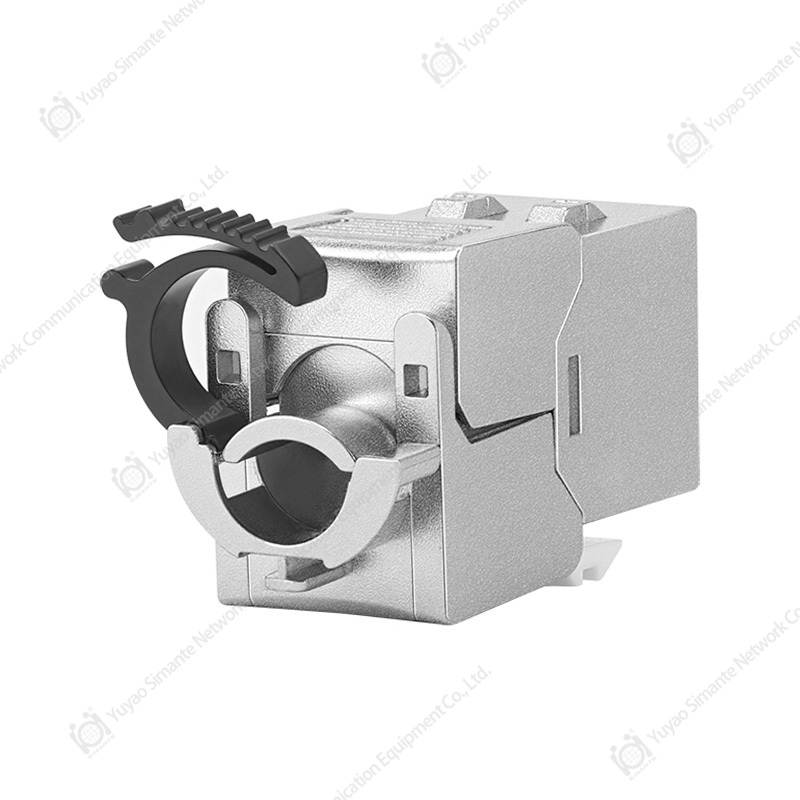
The SMT-1034T8C6A CAT6 Inline Coupler is designed for direct RJ45-to-RJ45 connection and network cable extension. It is suitable for communication sockets between equipment and work areas, as well as for embedded installation in compatible panels and patch panels. Its compact structure, straight-through connection, carefully arranged contacts, phosphor bronze gold-plated terminals, and PC polycarbonate housing make it a practical component for commercial buildings, data rooms, intelligent homes, automation systems, and other network environments.
This article examines the product’s construction, transmission characteristics, installation advantages, material selection, manufacturing strengths, environmental performance, packaging, and application value. It also explains how a professional network component manufacturer can support standard products, customized designs, OEM programs, and complete copper and fiber structured cabling projects.
1. The Role of an Inline Coupler in Structured Cabling
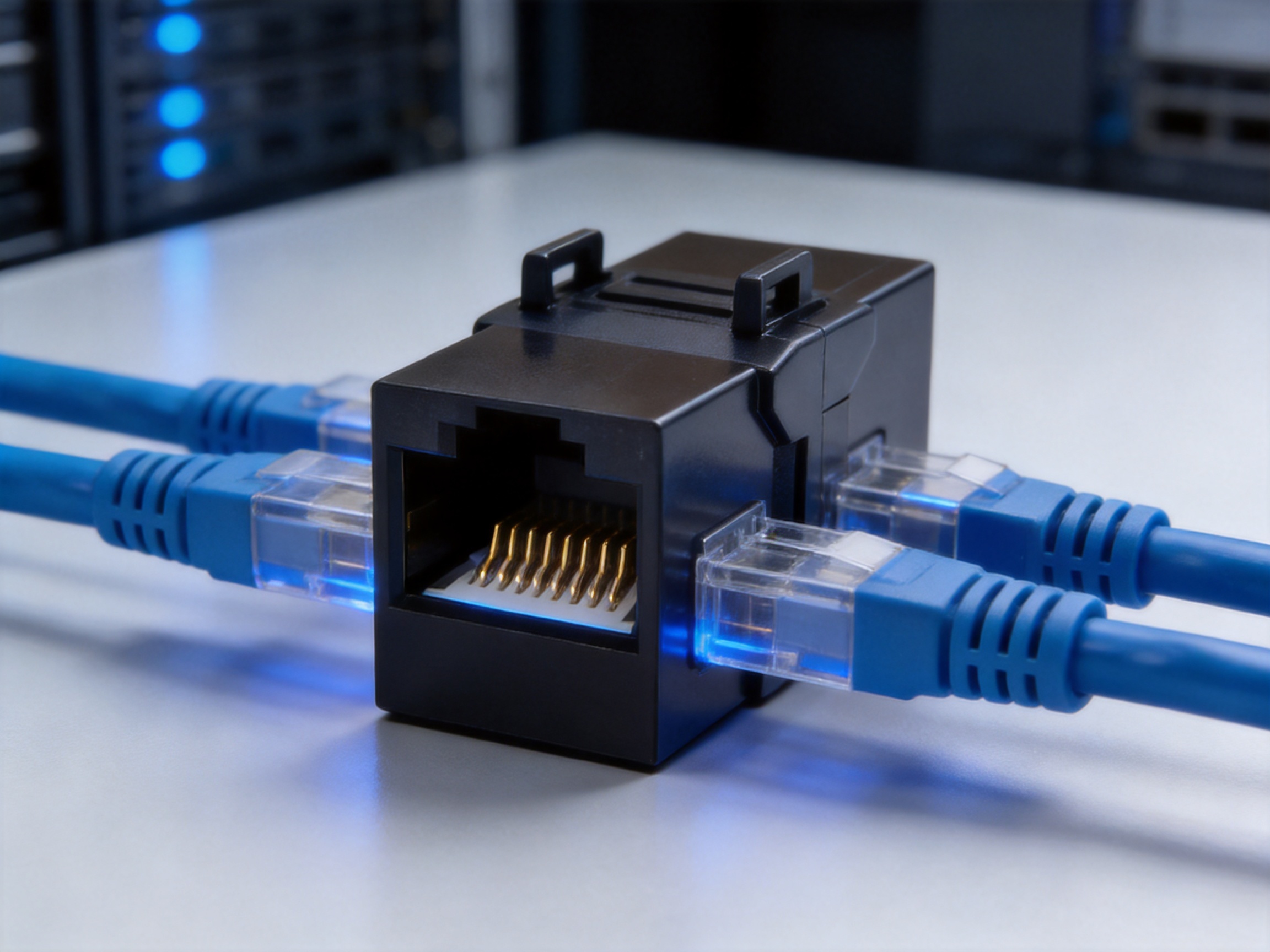
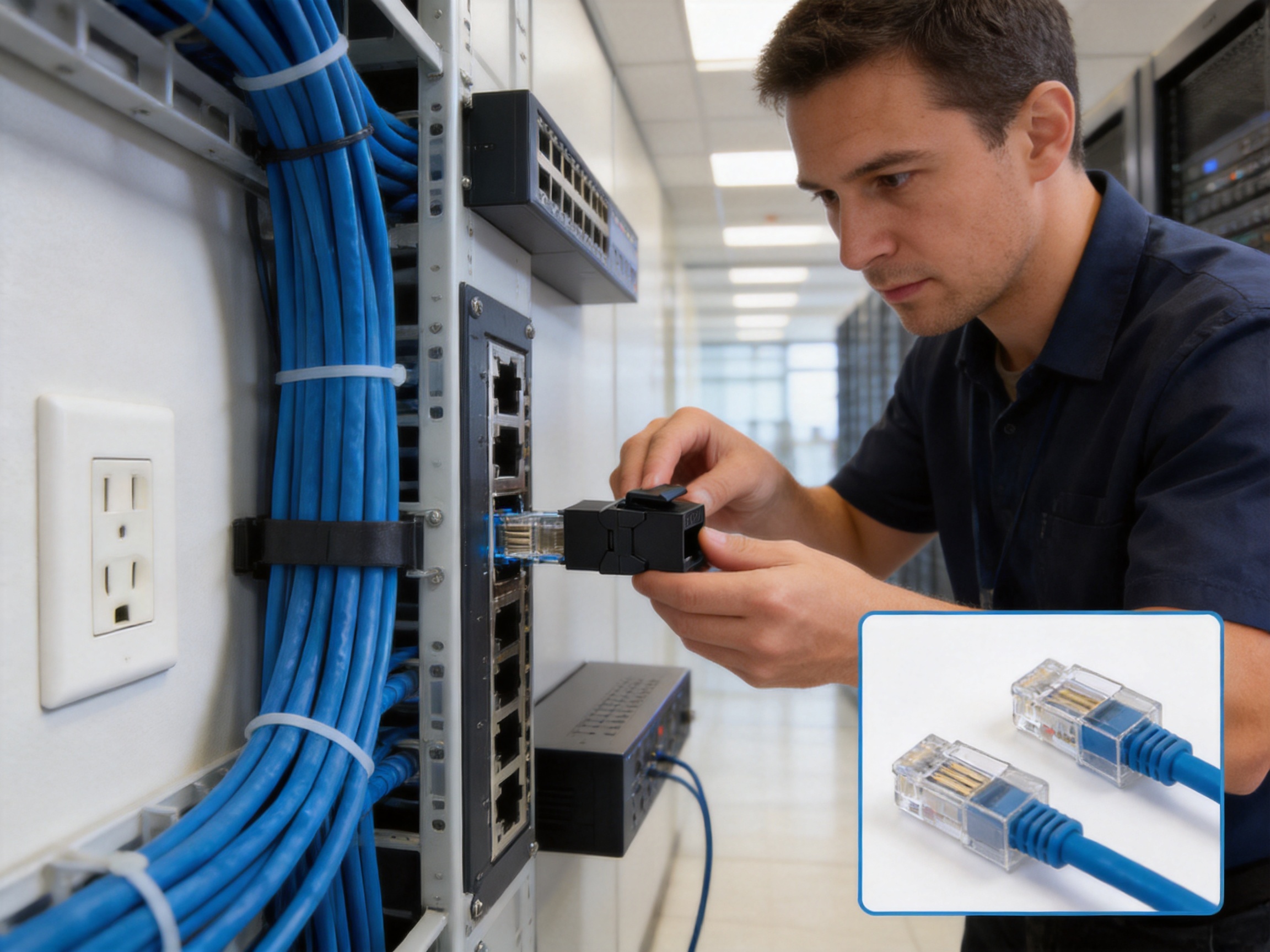
An inline coupler is a passive connection device with an RJ45 socket at each end. It allows two terminated network cables to be joined in a straight-through configuration. In practical installations, the device can extend a cable that is too short, connect a work-area outlet to a horizontal cable, provide an adapter point inside a panel, or simplify replacement and reconfiguration work.
Although an inline coupler is physically small, it is located directly in the signal path. Its contact geometry, conductor material, plating thickness, insulation design, and internal pair arrangement influence the quality of the connection. The product must therefore do more than simply hold two plugs. It must create stable electrical contact, control pair interaction, resist repeated insertion and removal, and remain mechanically secure during service.
The SMT-1034T8C6A is categorized as a CAT6 keystone jack and is developed for structured cabling applications. It follows T568A and T568B wiring sequence requirements, allowing installers to work with established network wiring practices. Because both ends use RJ45 crystal sockets, the product can connect two compatible RJ45 terminated cables without requiring special tools or complicated field procedures.
In a conventional installation, a cable may run from a patch panel to a wall outlet, from a floor distribution point to a workstation, or from a network device to a nearby connection point. When cable length, routing, equipment layout, or future changes create a need for an intermediate connection, the coupler offers a straightforward solution. It can also reduce the need to replace an entire cable when only the extension or connection arrangement needs to change.
2. Product Overview and Main Design Features
The SMT-1034T8C6A is engineered as a compact RJ45 inline coupler for CAT6-oriented structured cabling. Its primary function is to join two network cable assemblies through a one-to-one straight-through connection. This simple electrical architecture makes the product easy to understand, install, test, and maintain.
The coupler supports a frequency range of 1 to 500 MHz according to the supplied technical information. This broad operating range is suitable for demanding copper network applications where signal integrity, contact stability, and controlled crosstalk are important. The design is intended to meet category 6A transmission standards while remaining compatible with common CAT6 installation environments.
The body has an embedded design that can be used with suitable panels and patch panels. A card-position structure helps hold the network cable or module in place, improving installation order and reducing the chance of accidental movement. This feature is particularly valuable in high-density wiring locations where many cables may be routed close together.
Both ends of the coupler are RJ45 sockets. This configuration provides several practical benefits:
First, installers can connect pre-terminated patch cords or horizontal cables directly. No field termination is required at the coupler itself.
Second, the connection can be disconnected and reconnected during testing, equipment relocation, or maintenance.
Third, the coupler can be used as an adapter point between a fixed cable run and a replaceable patch cable.
Fourth, the compact format supports integration into a wider family of keystone-style components, including data sockets, wall face plates, and patch panels.
The internal contact pins use a high-and-low staggered arrangement. This contact arrangement is intended to reduce near-end crosstalk by improving the spacing and electrical relationship between relevant conductors. In structured cabling, crosstalk control is important because unwanted coupling between pairs can reduce signal quality and transmission margin.
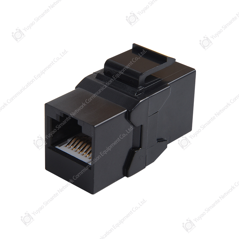
SMT-1034T8C6A CAT6 Inline Coupler
3. Transmission Performance and Electrical Characteristics
Network cabling performance is determined by the combined behavior of the cable, connector, patch panel, outlet, and other components in the permanent link or channel. An inline coupler must therefore provide a controlled connection that does not introduce excessive resistance, intermittent contact, insulation breakdown, or unwanted signal coupling.
3.1 Frequency Range
The specified frequency range is 1–500 MHz. A component designed for this range must maintain consistent electrical behavior across low, mid, and high frequencies. At higher frequencies, small changes in conductor geometry, contact alignment, dielectric material, or termination quality can have a greater effect on insertion loss, return loss, and crosstalk.
The 1–500 MHz range gives the coupler a useful operating margin for advanced copper structured cabling applications. It also reflects the importance of treating a connection module as a high-frequency component rather than as a simple mechanical adapter.
3.2 Straight-Through RJ45 Connection
The connection method is RJ45 crystal head 1-to-1 straight-through type. This means that the conductors are arranged to preserve the corresponding pin relationship from one end to the other. Installers can therefore use the coupler with cables terminated according to the applicable T568A or T568B wiring sequence, provided that the complete link is planned consistently.
A straight-through arrangement is especially useful when the coupler is placed between two existing cable assemblies. It avoids unnecessary crossover complexity and makes troubleshooting easier. If a link fails, each cable and the coupler can be tested as separate sections.
3.3 Near-End Crosstalk Control
The technical information specifies a near-end crosstalk attenuation NEXT value of at least 3 dB. The product’s staggered contact-pin design supports the effort to reduce near-end coupling between pairs. In a practical system, the final crosstalk result depends on the cable category, plug construction, termination quality, connector compatibility, and installation geometry.
The advantage of the high-and-low contact arrangement is that it addresses crosstalk at the connector interface itself. Rather than relying only on the cable’s internal pair separation, the coupler uses contact positioning to reduce parallel interaction in the connection area. This is an important design consideration in compact RJ45 modules where contact pins must be arranged within a limited space.
3.4 Dielectric Withstand
The coupler is specified to withstand DC 1000 V, or AC 750 V, for one minute without breakdown or arcing. This dielectric withstand characteristic indicates that the insulation system is designed to maintain separation between conductive elements under the stated test condition.
Such a test is relevant to product safety, manufacturing quality, and insulation reliability. It does not mean that the coupler should be connected to high-voltage circuits. The product is intended for low-voltage communication systems, and installation must always follow applicable electrical and network safety requirements.
| Technical Item | Specified Characteristic | Application Value |
|---|---|---|
| Frequency range | 1–500 MHz | Supports high-frequency copper network transmission |
| Connection type | RJ45 socket to RJ45 socket, 1-to-1 straight-through | Enables direct connection of two terminated network cables |
| Near-end crosstalk attenuation | At least 3 dB | Helps control pair-to-pair signal coupling |
| Withstand voltage | DC 1000 V or AC 750 V for one minute | Supports insulation integrity verification |
| Insertion force | Not more than 20 N | Allows practical installation without excessive effort |
| Pull-out force | Not less than 20 N | Helps maintain a secure connection |
| Connector connection device effect | 50 N | Provides a mechanical resistance reference |
| Plug and socket durability | 750 insertion cycles | Supports repeated service and maintenance operations |
| Operating temperature | -25°C to +70°C | Suitable for a broad range of indoor installation conditions |
| Relative humidity | Not more than 85% | Supports operation in controlled humid environments |
4. Mechanical Reliability and Service Life
A network connection must remain stable after installation, cable routing, equipment movement, and maintenance activity. Mechanical reliability is especially important in patch panels, wall outlets, work areas, and equipment cabinets where plugs may be handled repeatedly.
4.1 Controlled Insertion and Removal
The specified insertion force is not more than 20 N, while the pull-out force is not less than 20 N. These values represent a balance between usability and retention. The plug should not require excessive force during installation, yet it must remain securely engaged after insertion.
Controlled insertion force helps installers work efficiently in high-density locations. When many ports are installed close together, excessive insertion force can cause hand fatigue or place stress on the panel. A controlled pull-out force helps prevent accidental disconnection caused by cable movement, vibration, or routine handling.
4.2 Resistance to Connector Loading
The specified effect of the connector connection device is 50 N. This mechanical reference is relevant to the ability of the assembly to resist an applied load without unacceptable displacement or damage. In real installations, cable bundles can exert pulling, bending, or side-loading forces on connection modules. A well-designed coupler should be installed with appropriate cable support, but the product should also possess suitable mechanical strength.
4.3 Durability Under Repeated Use
The product is specified for 750 plug-and-socket insertion cycles. This durability level supports repeated testing, service, reconfiguration, and equipment replacement. It is particularly useful for data centers, laboratories, network rooms, offices, and smart-building projects where ports may be accessed more frequently than in a fixed residential installation.
Durability depends on the interaction of the RJ45 plug, contact spring, plating, housing, and mechanical retention structure. Gold-plated phosphor bronze contacts help reduce surface oxidation and maintain a stable conductive interface when the connection is repeatedly operated under normal conditions.
5. Materials and Surface Treatment
Material selection has a direct effect on the electrical, mechanical, environmental, and manufacturing performance of a coupler. The SMT-1034T8C6A uses phosphor bronze for the gold-plated contact pins, PC polycarbonate for the plastic housing, and FR4 for the PCB material identified in the product information.
5.1 Phosphor Bronze Contacts
Phosphor bronze is widely used in electrical connectors because it combines good conductivity with spring properties and mechanical resilience. The contact must deflect when an RJ45 plug is inserted and then maintain pressure against the plug contact surface. If the material loses spring force, the connection may become unstable over time.
The use of phosphor bronze helps the contact system withstand repeated insertion and removal while preserving the mechanical force needed for electrical continuity. It also provides a practical balance between performance, manufacturability, and cost.
5.2 Gold-Plated Contact Surface
The specified gold-plated layer thickness is 6–50U. Gold plating is used on connector contact surfaces because it provides strong resistance to oxidation and corrosion under appropriate operating conditions. A stable contact surface can help reduce contact resistance and improve long-term connection reliability.
The actual plating requirement should be selected according to the application, expected service environment, mating cycles, and customer specification. A controlled plating process is important because insufficient or uneven plating may reduce durability, while unnecessary over-specification may increase cost without providing proportional value.
5.3 PC Polycarbonate Housing
The non-metallic housing uses PC polycarbonate. Polycarbonate is valued for its impact resistance, dimensional stability, and suitability for injection molding. These characteristics are useful in a small connector body that must maintain precise internal alignment while also resisting normal handling during installation.
A stable plastic housing supports consistent spacing between contact elements and helps protect the internal connection from accidental contact with surrounding components. It also makes the module lightweight, compact, and suitable for integration into keystone-style panels.
5.4 FR4 PCB Material
FR4 is identified as the PCB material. FR4 is a glass-fiber-reinforced epoxy laminate commonly used in electronic and connector assemblies. Its strength, insulation performance, dimensional stability, and established manufacturing ecosystem make it suitable for compact module construction.
When FR4 is combined with controlled contact geometry and a protective housing, it can contribute to a stable internal platform for the connector assembly. Material quality, board thickness, copper pattern accuracy, and soldering or assembly control remain important factors in the finished product.
6. Embedded Installation and System Compatibility
The embedded design allows the coupler to be used with panels and patch panels that accept compatible keystone-style modules. This gives system designers flexibility when planning wall outlets, distribution frames, work-area connections, and equipment cabinets.
In a wall face plate, the coupler can provide a compact service point for joining a permanent cable section with a patch cable. In a patch panel, it can support organized port presentation and simplify cross-connection. In a custom enclosure, it can be integrated as an intermediate connection without requiring a large standalone adapter.
The card-position structure helps hold the module in the selected opening. Secure mounting is important because a loose module can move when cables are inserted or removed. Movement can increase mechanical stress on the cable and may make service work more difficult.
Compatibility should always be confirmed before installation. The panel opening, module dimensions, retaining clips, cable bend radius, and RJ45 plug design should be checked. The coupler is intended to inter-match with connectors of the same standard series. Mixing components from different standards or incompatible mechanical families may create fit, retention, or performance problems.
6.1 T568A and T568B Considerations
The product information states that the coupler is suitable for T568A and T568B line sequences. Both wiring schemes use the same twisted pairs but assign colors to pins differently. A structured cabling installation should maintain a consistent wiring plan and clearly label each cable and termination.
For a straight-through connection, the corresponding pin relationship must be maintained across the complete assembly. The coupler itself should not be treated as a substitute for correct cable termination. Installers should verify the wiring sequence with a qualified cable tester after installation.
6.2 Copper Cable Compatibility
The product is designed to mate with copper-axis twisted pair cables and copper-axis jumpers as described in the supplied information. In practical terms, it is intended for compatible copper Ethernet cabling and RJ45 patch cords. The cable category, conductor size, plug type, shielding arrangement, and jacket diameter should be matched to the project requirements.
Where shielded cable is required, installers should confirm whether the specific coupler and panel system provide the necessary shielding continuity. The product information describes the supplied module as a compact RJ45 coupler, so the grounding and shielding requirements of a particular installation should be verified separately.
7. Application Areas
7.1 Commercial Buildings
Office buildings often require flexible connections between communication rooms, floor distribution points, workstations, wireless access points, printers, telephones, cameras, and building-management devices. An inline coupler can provide a convenient connection point when office layouts change or when cable routing needs to be extended.
Its compact format helps maintain a clean appearance inside face plates and patch panels. The RJ45 interface also makes it familiar to installers and end users, reducing the need for specialized connection procedures.
7.2 Data Rooms and Equipment Cabinets
In equipment rooms, space is limited and cable identification is critical. A keystone-style coupler can be integrated into a modular panel, allowing installers to create a structured and labeled connection field. The ability to disconnect and reconnect cables also supports troubleshooting and equipment replacement.
Because data rooms may experience frequent service activity, mechanical durability and stable contact performance are valuable. The specified 750 insertion cycles provide a useful reference for repeated connection operations under normal conditions.
7.3 Smart Homes and Building Automation
Smart-home and building-automation systems use network connections for control panels, sensors, gateways, access-control devices, cameras, lighting systems, and HVAC equipment. These applications often involve distributed cabling and equipment that may be updated during the life of the building.
An inline coupler allows network extensions and modular connection points without requiring a complete cable replacement. The compact design is suitable for installation near control cabinets, communication boxes, wall outlets, and low-voltage equipment enclosures.
7.4 Industrial and Automation Environments
Automation installations may use Ethernet connections between controllers, human-machine interfaces, industrial computers, sensors, and network switches. The operating temperature specification of -25°C to +70°C provides a broad reference range for many controlled indoor environments.
However, industrial users should evaluate vibration, dust, oil exposure, electromagnetic interference, humidity, and mechanical loading before selecting any connector. Where harsh-environment protection is required, the complete enclosure and cable system must be designed accordingly.
7.5 Maintenance and Network Expansion
When an existing cable does not reach a new equipment location, an inline coupler can provide a faster alternative to removing and replacing the original cable. It is also useful for temporary testing, equipment relocation, and network expansion projects.
For permanent installations, the coupler should be secured and documented as part of the link. It should not be left unsupported in a location where cable weight or bending force can damage the connection. Proper strain relief and bend-radius control remain essential.
8. Advantages Compared with Generic Inline Adapters
Not all RJ45 couplers provide the same level of performance or manufacturing consistency. Low-cost generic adapters may use inconsistent contact materials, thin or poorly controlled plating, weak retention structures, or plastic housings that do not hold the internal components accurately.
The SMT-1034T8C6A offers several advantages that are relevant when comparing it with basic unverified couplers.
8.1 Category-Oriented Electrical Design
The coupler is designed around category 6A transmission requirements and a frequency range reaching 500 MHz. This indicates a more deliberate approach to high-frequency electrical design than a simple mechanical joining block. The high-and-low contact-pin arrangement is intended to improve crosstalk control at the interface.
8.2 Stable Contact Materials
Phosphor bronze contacts provide spring performance and mechanical durability, while gold plating helps protect the mating surface from oxidation. Together, these materials can support more consistent performance over repeated service than unplated or poorly specified contacts.
8.3 Robust Mechanical Parameters
The stated insertion, pull-out, connection-load, and durability values provide measurable references for engineering selection. Buyers and system integrators can evaluate the product using defined characteristics rather than relying only on appearance or general product descriptions.
8.4 Modular Installation
The embedded keystone-style design makes the product easier to integrate into modular panels and patch panels. A generic external adapter may require additional mounting hardware or occupy more space. The compact module format helps produce a cleaner and more maintainable system.
8.5 Quality and Customization Support
The manufacturer operates multiple regular and customization production lines, including automatic and semi-automatic injection molding equipment and automatic assembly machines. This manufacturing base supports stable volume production while also allowing customer-specific requirements to be evaluated.
Customization may include packaging, labeling, color, module configuration, branding, panel integration, and other project-specific requirements, subject to technical review. OEM and ODM capability is especially valuable for distributors, system integrators, and structured cabling brands that require consistent product identity across multiple markets.
9. Manufacturing Process and Quality Strengths
The performance of a network coupler is strongly influenced by manufacturing control. Precision molding, contact stamping, plating, assembly, inspection, and packaging must work together. A mature production system reduces variation between batches and supports predictable installation results.
9.1 Product Design and Development
The manufacturer maintains a research and development system supported by engineers and technical personnel. This type of technical structure allows product designs to be reviewed from electrical, mechanical, material, tooling, assembly, and application perspectives.
For a connector product, design quality begins with accurate control of the contact layout, housing dimensions, mating geometry, retention structure, and panel interface. Engineers must consider not only the product’s initial performance but also its behavior after repeated use and under environmental stress.
9.2 Injection Molding Capability
The factory has automatic injection molding machines and semi-automatic injection molding machines. This capability is important for producing PC polycarbonate housings with repeatable dimensions and consistent appearance.
Injection molding quality depends on mold precision, resin preparation, temperature control, injection pressure, cooling conditions, cycle time, and part inspection. Stable process control helps ensure that contact cavities, clips, mounting features, and external surfaces remain within the required dimensional range.
Automatic equipment can improve repeatability and production efficiency, while semi-automatic equipment can provide flexibility for different product models, smaller batches, and customization projects. The combination of both types of equipment supports a broader range of customer requirements.
9.3 Contact Assembly and Automation
The factory uses automatic installation equipment for connector assembly. Automated or semi-automated assembly can help control the position, orientation, and seating of contact elements. This is particularly important for a compact RJ45 module where small alignment errors may affect mating reliability or electrical performance.
Automation also supports production consistency at higher volumes. When the same product is assembled repeatedly, controlled equipment can reduce variation caused by manual handling. Skilled technical personnel remain important for setup, inspection, process improvement, and exception management.
9.4 Performance Testing
The company emphasizes performance testing to meet customer requirements. For a CAT6 inline coupler, appropriate testing may include electrical continuity, wiring sequence, contact resistance, insulation resistance, dielectric withstand, mechanical retention, insertion and withdrawal behavior, and visual inspection.
Depending on the customer program, additional testing may be performed for transmission performance, crosstalk, environmental resistance, salt spray, dimensional accuracy, and packaging integrity. A product that is tested at several stages provides greater confidence than one evaluated only through final visual inspection.
9.5 Production Scale
The factory maintains more than nine million units of annual output across its product range. Production scale can provide advantages in raw-material purchasing, process development, tooling investment, equipment utilization, and quality-system learning.
Scale alone does not guarantee quality, but when combined with technical management and production controls, it can support stable supply for large structured cabling projects. It also helps the manufacturer serve distributors and contractors that require consistent replenishment over extended project periods.
10. Environmental Performance and Compliance
The product information states that the coupler meets RoHS requirements. Restriction of hazardous substances is an important consideration for modern electrical and electronic products, particularly when components are used in commercial construction, public infrastructure, export projects, and environmentally regulated markets.
The specified operating temperature range is -25°C to +70°C. The stated humidity requirement is not more than 85%, with the supplied information also referring to a temperature and humidity condition of 85°C ±3°C. Because these values may represent different test or operating conditions, project engineers should confirm the exact test interpretation and qualification method before applying the product to an unusual environment.
Normal installation should avoid prolonged exposure to condensation, corrosive chemicals, oil, direct water, excessive dust, and ultraviolet radiation unless the complete system has been designed for such conditions. A connector’s environmental rating is only one part of system reliability; enclosure protection, cable jacket selection, ventilation, drainage, and installation practice are equally important.
10.1 Salt Spray Test Conditions
The supplied salt spray requirements specify a salt solution pH between 6.5 and 7.2 before atomization at 35°C ±2°C. The solution is prepared from chemically pure or analytically pure sodium chloride and distilled or deionized water, with a concentration of 5% ±0.1% by mass.
Continuous atomization is recommended for 48 hours. During atomization, contamination from oil and dust should be prevented, and the temperature and humidity of the spray air should not improperly affect the test space.
Salt spray testing is useful for evaluating the corrosion resistance of exposed metallic surfaces and plating systems. It is not a direct prediction of every real-world service environment, but it provides a controlled comparative test. Gold-plated phosphor bronze contacts and appropriate housing materials can contribute to improved resistance when the product is manufactured and stored correctly.
11. Installation Best Practices
Correct installation is necessary to realize the performance of any connector. Before installation, technicians should confirm the cable category, connector type, wiring sequence, panel compatibility, and intended use of the coupler.
Use compatible RJ45 plugs and cables. Do not force a plug into the socket if the latch, boot, shield, or cable diameter prevents proper seating. The plug should click into position, and the latch should remain accessible for future removal.
Support the cable close to the coupler. The coupler should not carry the full weight of a long cable or bundle. Excessive pulling force can transfer stress to the plug, contact springs, housing, or panel retention clips.
Respect the minimum bend radius of the connected cables. Sharp bends near the RJ45 plug can affect pair geometry and increase mechanical stress. Cable management should preserve a smooth route into and away from the module.
Keep the connection clean. Dust, oil, moisture, and foreign particles can affect the mating interface. If cleaning is required, use a method approved for network connectors and avoid abrasive materials that may damage the plating.
Test the completed link. A cable tester can verify continuity, pin assignment, pair mapping, and common wiring errors. For higher-performance installations, certification testing should be carried out according to the project’s category and standards requirements.
Label the connection. Documentation should identify the cable source, destination, coupler location, panel position, and any extension point. Clear records reduce troubleshooting time and make future changes safer.
12. Packaging, Storage, and Logistics
The product is placed in a special blister bag and then packed in a cardboard box. Accessories are placed together with the product, and a label showing the model and quantity is affixed to the upper-left area of the front of the carton. This packaging arrangement is intended to protect the small module during handling, storage, and transportation while helping customers identify the contents.
The regular packing quantity is 50 pieces per box, with 10 boxes per carton, for a total of 500 pieces per carton. This configuration is suitable for distributors, contractors, and project procurement teams that need standardized inventory units.
Packaged products should be stored in a warehouse with an ambient temperature of -5°C to +30°C and relative humidity not exceeding 70%. The surrounding air should be free from acid, alkali, and other corrosive gases. The stated storage period is three years under the specified conditions.
Good storage practice includes keeping cartons off the floor, preventing crushing or water exposure, avoiding direct sunlight, and maintaining stock rotation. Packaging should remain sealed until products are ready for inspection or installation. If products have been stored for a long period, the package and contact surfaces should be visually checked before use.
13. Manufacturer Capabilities and Supply Advantages
Yuyao Simante Network Communication Equipment Co., Ltd. is a professional manufacturer of network cabling solutions and optical fiber products. Its product range includes keystone jacks, patch panels, wall face plates, data sockets, and related structured cabling components.
The company integrates design, development, sales, and service. This integrated model can simplify communication for customers because product development, technical clarification, manufacturing, packaging, and after-sales support are connected within one organization.
With nearly 20 years of service experience, the company has developed expertise in network communication equipment and structured cabling applications. Its engineering and technical teams support product improvement, quality management, and customer-specific project requirements.
The company maintains more than 10 engineers and more than 30 full-time technical personnel. This technical workforce can contribute to tooling development, production-line support, quality testing, process optimization, and customization assessment.
Ten regular and customization production lines support both standard catalog products and project-specific requirements. This is useful for customers that need a stable standard item as well as customers that require modified dimensions, packaging, color, labeling, or product combinations.
The manufacturer exports to Europe, Australia, Africa, the Middle East, and Southeast Asia. Experience in multiple markets can help the company understand differences in packaging, documentation, quality expectations, and project purchasing procedures.
OEM and ODM projects are also accepted. OEM service can support customers that want products manufactured under their own brand or packaging system. ODM service can support customers that need assistance with product development, structural adaptation, tooling, or a complete application-specific solution.
14. Copper and Fiber Structured Cabling Portfolio
Although the SMT-1034T8C6A is a copper RJ45 product, it belongs to a broader structured cabling portfolio that includes copper and optical fiber components. A supplier with capabilities in both areas can help customers coordinate components across complete data cabling systems.
Copper products may include keystone jacks, patch panels, wall face plates, data outlets, couplers, and other modular connection products. Fiber products may include fiber adapters, optical distribution components, patch cords, termination accessories, and related passive equipment, depending on the customer’s project requirements.
A combined copper and fiber supplier can be valuable for commercial buildings, data centers, campuses, industrial networks, smart homes, and communication infrastructure projects. Customers may reduce sourcing complexity by coordinating multiple component categories with one experienced manufacturer.
The most effective structured cabling solution is not based on one product alone. It requires compatibility among cable, connector, panel, cabinet, pathway, labeling system, grounding arrangement, testing method, and maintenance plan. A manufacturer that understands the complete system can provide more useful technical guidance than a supplier focused only on individual parts.
15. Selection Guide for Project Buyers
When evaluating an inline coupler, buyers should consider more than unit price. The correct product should match the transmission category, mechanical format, installation environment, cable type, service expectations, and documentation requirements.
Confirm the required category performance. If the project calls for CAT6A-oriented performance, the coupler and all mating components should be selected as part of a compatible category system.
Review the frequency range and electrical specifications. High-frequency performance, crosstalk behavior, insulation withstand, and contact reliability can influence the certification result of the entire link.
Check the panel interface. A keystone-style product should fit the selected face plate, patch panel, or enclosure. Verify the retaining clips and module dimensions before ordering large quantities.
Evaluate material and plating specifications. Phosphor bronze contacts, gold plating, polycarbonate housing material, and FR4 construction provide useful reference points for comparing suppliers.
Consider service frequency. A connection point that will be accessed often should have a suitable insertion-cycle rating and strong retention performance.
Confirm environmental requirements. Temperature, humidity, salt exposure, chemical contamination, vibration, and enclosure conditions should be considered together.
Ask about quality documentation. Depending on the project, customers may require inspection reports, material declarations, RoHS documentation, test records, packaging specifications, or samples for qualification.
Review supply capability. A manufacturer with stable production lines, technical staff, and experience in export markets can help reduce the risks associated with delayed delivery, inconsistent batches, or difficult customization.
16. Why Manufacturing Process Matters to Competitiveness
In the competitive network component market, product advantages are created by the combination of engineering, materials, process control, quality testing, and customer service. A coupler may look similar to competing products from the outside, but internal contact geometry, plating quality, plastic precision, and assembly consistency can be substantially different.
Advanced manufacturing equipment supports repeatability. Automatic injection molding helps maintain housing dimensions. Automatic assembly equipment supports accurate component placement. Skilled engineers improve tooling and process parameters. Technical personnel monitor production and respond to quality issues.
Testing converts design intentions into measurable results. Electrical tests verify continuity and insulation. Mechanical tests examine insertion, pull-out, loading, and durability. Environmental tests evaluate resistance to heat, humidity, and corrosion. Visual and dimensional inspections help prevent obvious defects from reaching the customer.
Manufacturing scale creates another competitive advantage when it is properly managed. Larger output capability can support stable supply, while customization lines provide flexibility for smaller special projects. The ability to handle both standard and customized orders can be important for distributors and system integrators serving different markets.
Customer communication is also part of manufacturing strength. Technical questions about cable compatibility, panel integration, packaging, labeling, and test requirements should be answered before mass production. Early clarification reduces the chance of expensive changes after production begins.
17. Project Value and Total Cost Considerations
The purchase price of an inline coupler is only one part of its total cost. Installation time, testing effort, replacement frequency, service access, inventory management, and the consequences of connection failure can be more important over the life of a network.
A compact embedded design can reduce installation complexity by fitting directly into compatible panels. RJ45 sockets allow the use of pre-terminated cable assemblies and avoid field termination at the coupler. Stable contacts and mechanical retention can reduce troubleshooting and accidental disconnection.
Standardized packaging helps distributors and contractors manage inventory. The 50-piece box and 500-piece carton quantities provide predictable ordering units. Customer-specified packaging can further support private-label sales, project identification, or regional distribution requirements.
When the product is used in a complete structured cabling system, its value also comes from compatibility with related components. A supplier capable of producing keystone jacks, patch panels, wall outlets, data sockets, copper accessories, and optical fiber products can help standardize a project and simplify procurement.
18. Frequently Asked Questions
Q1. What is the main function of the SMT-1034T8C6A?
The product joins two RJ45-terminated network cables through a one-to-one straight-through connection. It can extend a network cable, provide an intermediate connection point, or connect horizontal cabling with work-area cabling.
Q2. Is the product suitable for CAT6A-oriented applications?
The product information states that it meets category 6A transmission standards and supports a frequency range of 1–500 MHz. For a complete CAT6A-certified link, the cable, plugs, panels, installation method, and testing procedure must also meet the required category specifications.
Q3. Can it be installed in a patch panel?
Yes. The embedded design is intended for use with compatible panels and patch panels. The exact panel opening and retaining structure should be confirmed before installation.
Q4. Does the coupler support T568A and T568B?
The product is described as suitable for T568A and T568B line sequences. Installers should use a consistent wiring plan and verify the completed cable assembly with an appropriate tester.
Q5. What type of contact material is used?
The contact pins are made from phosphor bronze and are gold plated. The specified gold-plated layer thickness is 6–50U.
Q6. What plastic is used for the housing?
The listed non-metallic housing material is PC polycarbonate. This material supports impact resistance, dimensional stability, and precision injection molding.
Q7. How many insertion cycles are specified?
The specified durability is 750 plug-and-socket insertion cycles. Actual service life can depend on plug quality, environmental conditions, handling, and installation practices.
Q8. What is the specified operating temperature?
The stated environmental temperature range is -25°C to +70°C. Projects with condensation, chemical exposure, outdoor conditions, or severe industrial stress should receive a separate environmental suitability review.
Q9. Is the product RoHS compliant?
The supplied product information states that the product meets RoHS standards. Customers requiring formal compliance documentation should request the applicable declaration or test records for their purchasing program.
Q10. What are the regular packing quantities?
The regular packing quantity is 50 pieces per box, with 10 boxes per carton, for a total of 500 pieces per carton.
Q11. Can the packaging be customized?
The product note indicates customer-specified packaging is available. Packaging details, labeling, carton markings, and accessory arrangements should be confirmed before production.
Q12. Does the manufacturer support OEM and ODM projects?
Yes. The company undertakes OEM and ODM projects and operates both regular and customization production lines. Technical feasibility, tooling, minimum order quantity, testing, and packaging requirements should be discussed for each project.
Q13. How should the coupler be tested after installation?
At minimum, installers should verify continuity and pin assignment using a suitable cable tester. For high-performance structured cabling, permanent-link or channel certification testing should be conducted according to the project requirements.
Q14. Can the product be used outdoors?
The listed temperature and humidity values do not by themselves establish outdoor or weatherproof suitability. Outdoor use requires appropriate enclosure protection, cable selection, sealing, drainage, ultraviolet resistance, and environmental qualification.
19. Conclusion
The SMT-1034T8C6A CAT6 Inline Coupler is a compact and practical component for extending, organizing, and maintaining copper structured cabling systems. Its RJ45-to-RJ45 straight-through connection supports direct use with terminated network cables, while the embedded keystone-style design enables integration into compatible panels and patch panels.
Its main technical advantages include a 1–500 MHz frequency range, a staggered contact-pin arrangement designed to reduce near-end crosstalk, phosphor bronze gold-plated contacts, PC polycarbonate housing, FR4 construction, defined mechanical retention, and a 750-cycle durability specification. These features make it more than a basic cable joiner; they provide a structured approach to electrical performance, mechanical reliability, and installation flexibility.
The manufacturer strengthens the product offering through engineering resources, automatic and semi-automatic injection molding, automated assembly equipment, multiple regular and customization production lines, performance testing, international supply experience, and OEM and ODM support. This combination is valuable for customers seeking dependable components for individual installations as well as complete copper and fiber structured cabling programs.
For project buyers, distributors, contractors, and system integrators, the product provides a balance of compact design, standardized connection, material quality, serviceability, and manufacturing support. When selected with compatible cables and panels and installed according to professional cabling practices, it can contribute to cleaner, more flexible, and more maintainable network infrastructure.
References
1. YD/T 926.1-2009, General Specification for Communication Cables and Related Structured Cabling Components.
2. T568A and T568B balanced twisted-pair cabling wiring conventions.
3. RoHS principles for the restriction of hazardous substances in electrical and electronic equipment.
4. General practices for RJ45 connector installation, cable testing, and structured cabling maintenance.
5. Product technical information for the SMT-1034T8C6A CAT6 Inline Coupler.
6. Manufacturer information concerning copper and fiber structured cabling systems, production capabilities, quality testing, OEM, and ODM services.