Español
 عربى
عربى русский
Content
- 1 Understanding the Role of a Fiber Optical Patch Panel
- 2 Core Product Configuration
- 3 Advantages of the Sliding Design
- 4 High-Density 48-Port Organization in a 2U Space
- 5 SC-LC Connectivity for Flexible Network Design
- 6 Protection and Fiber Management
- 7 Installation and Maintenance Efficiency
- 8 Benefits Compared with Basic Fixed Patch Panels
- 9 Advantages Over Inadequately Designed High-Density Products
- 10 Manufacturing Strengths of the Supplier
- 11 Design Quality from the Source
- 12 Quality Control and Performance Testing
- 13 OEM and ODM Project Support
- 14 Applications in Different Network Environments
- 15 Recommended Installation Practices
- 16 How to Select the Correct Configuration
- 17 Why Manufacturer Experience Matters
- 18 Purchasing and Project Planning Considerations
- 19 Operational Value Over the Product Life Cycle
- 20 Q&A
- 20.1 What is the SMT-2206-48P-2U?
- 20.2 What does the 2U designation mean?
- 20.3 What is the advantage of a sliding patch panel?
- 20.4 Is the panel suitable for both SC and LC connectors?
- 20.5 Does the panel include fiber pigtails or splice accessories?
- 20.6 Where can this product be used?
- 20.7 How should the panel be maintained?
- 20.8 Can the product be customized?
- 20.9 What manufacturing capabilities support this product?
- 20.10 What should be confirmed before placing an order?
- 21 Conclusion
- 22 References
- 23 Product: SMT-2206-48P-2U Sliding type SC-LC Rack Mount Fiber Optical Patch Panel 2U
Modern communication networks depend on dependable fiber management as much as they depend on high-performance cables, switches, and transmission equipment. As data centers, enterprise networks, telecommunications facilities, security systems, and industrial installations continue to expand, fiber infrastructure must be organized in a way that supports stable operation, efficient maintenance, and future upgrades. A well-designed fiber optical patch panel is therefore more than a passive enclosure. It is a practical connection platform that protects fiber terminations, simplifies administration, and creates a controlled interface between backbone cables and active network equipment.
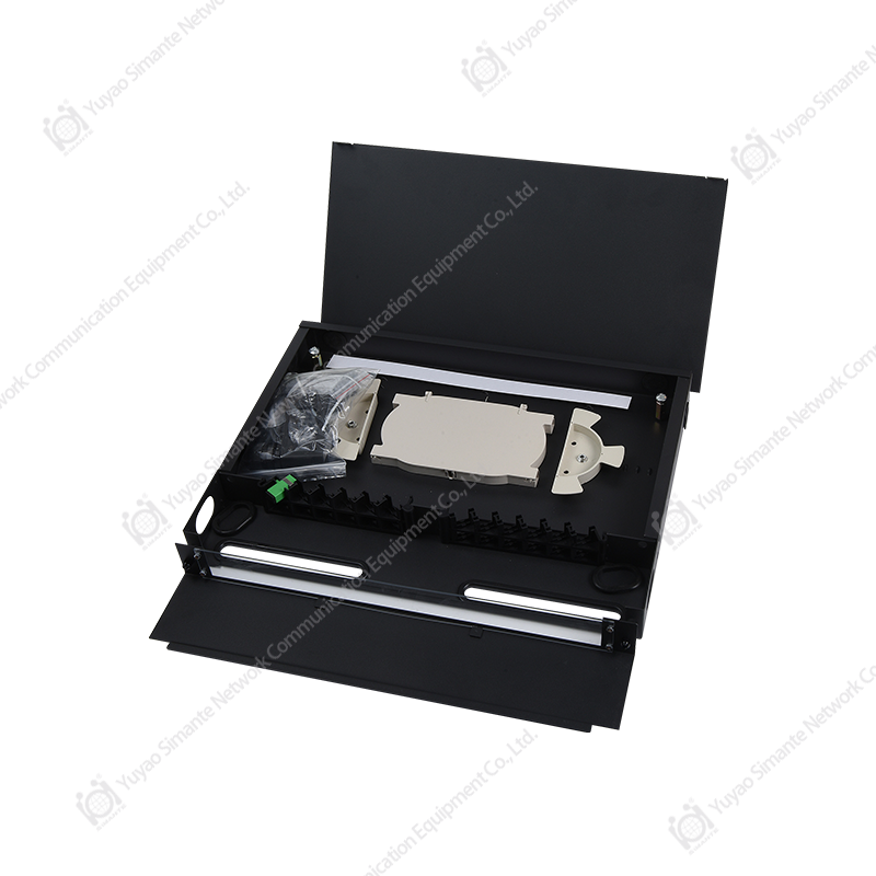
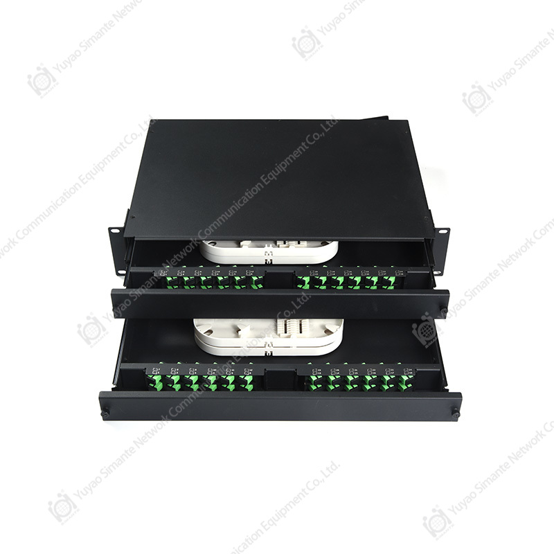
The SMT-2206-48P-2U Sliding Type SC-LC Rack Mount Fiber Optical Patch Panel 2U is designed for this important role. With a 2U rack-mount form factor, a high-density 48-port configuration, and support for SC-LC fiber connectivity, the panel provides a structured solution for organizing and protecting fiber connections in standard equipment cabinets and racks. Its sliding design improves access to internal components, helping installers and maintenance teams perform termination inspection, patching, labeling, testing, and troubleshooting more efficiently.
This article examines the product’s construction concept, operational benefits, installation value, application potential, and suitability for professional structured cabling projects. It also explains how the manufacturing capabilities of Yuyao Simante Network Communication Equipment Co., Ltd. support consistent product quality, customization, and long-term supply requirements.
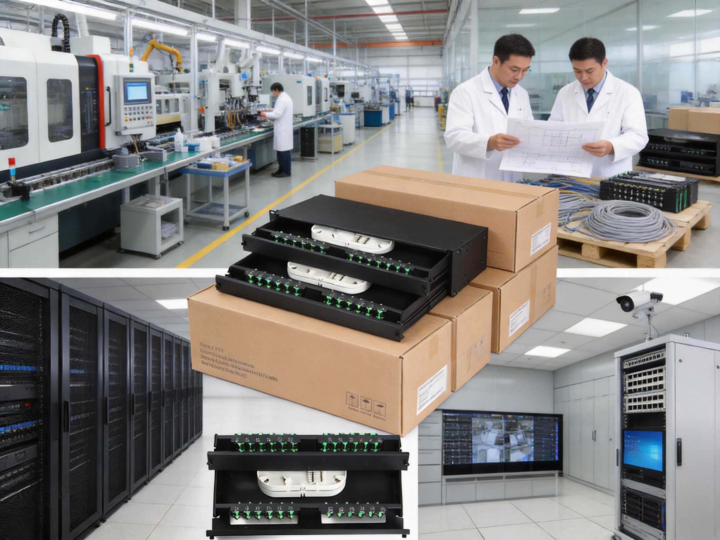
SMT-2206-48P-2U Sliding type SC-LC Rack Mount Fiber Optical Patch Panel 2U
Understanding the Role of a Fiber Optical Patch Panel
A fiber optical patch panel provides a controlled point for fiber cable termination and cross-connection. In a typical structured cabling system, backbone fiber cables enter a rack or cabinet and are terminated within an enclosure. Short fiber patch cords then connect the terminated fibers to switches, optical distribution equipment, media converters, or other network devices. This arrangement separates permanent cabling from equipment connections and makes the network easier to manage.
Without a dedicated patching enclosure, fiber cables may be routed directly to active equipment. Direct routing can create several problems, including excessive cable movement, difficult identification, poor bend management, and increased risk of accidental disconnection. A patch panel establishes a clear boundary between the fixed cabling plant and the equipment layer. It also provides a central location for port numbering, cable documentation, testing, and planned service changes.
The SMT-2206-48P-2U is intended for applications in which a comparatively large number of fiber connections must be accommodated within a limited rack space. Its 48-port capacity helps network designers consolidate connections and preserve valuable cabinet space. The 2U height provides room for organized internal fiber management while allowing the enclosure to be installed with other network equipment in a standard rack environment.
The panel is particularly suitable for structured cabling systems that use SC and LC interfaces. SC connectors are widely used in many backbone and telecommunications applications because of their push-pull coupling design and straightforward handling. LC connectors are frequently selected where higher port density is required. A panel supporting SC-LC connectivity can therefore serve projects that require practical compatibility between different connector formats or specific adapter configurations.
Core Product Configuration
The product name identifies the principal characteristics of the enclosure: SMT-2206-48P-2U, sliding type, SC-LC, rack mount, fiber optical patch panel, and 2U. Each designation communicates an important part of its intended use.
| Feature | Product Configuration | Practical Value |
|---|---|---|
| Product type | Fiber optical patch panel | Provides an organized termination and cross-connection point for fiber networks. |
| Rack format | 2U rack-mount design | Uses standard rack space and supports orderly cabinet planning. |
| Port capacity | 48 ports | Supports high-density fiber administration in a compact enclosure. |
| Access structure | Sliding type | Allows the working area to be brought forward for inspection and maintenance. |
| Connector compatibility | SC-LC configuration | Supports projects involving SC and LC fiber interface arrangements. |
| Primary application | Structured fiber cabling | Suitable for data communication, telecommunications, security, and equipment-room installations. |
Actual adapter style, fiber count arrangement, pigtail configuration, splice organization, and other detailed specifications should be confirmed against the required project configuration before ordering. This is especially important when the panel is being integrated into a system with particular connector polishing types, fiber modes, cable entry methods, or labeling standards.
Advantages of the Sliding Design
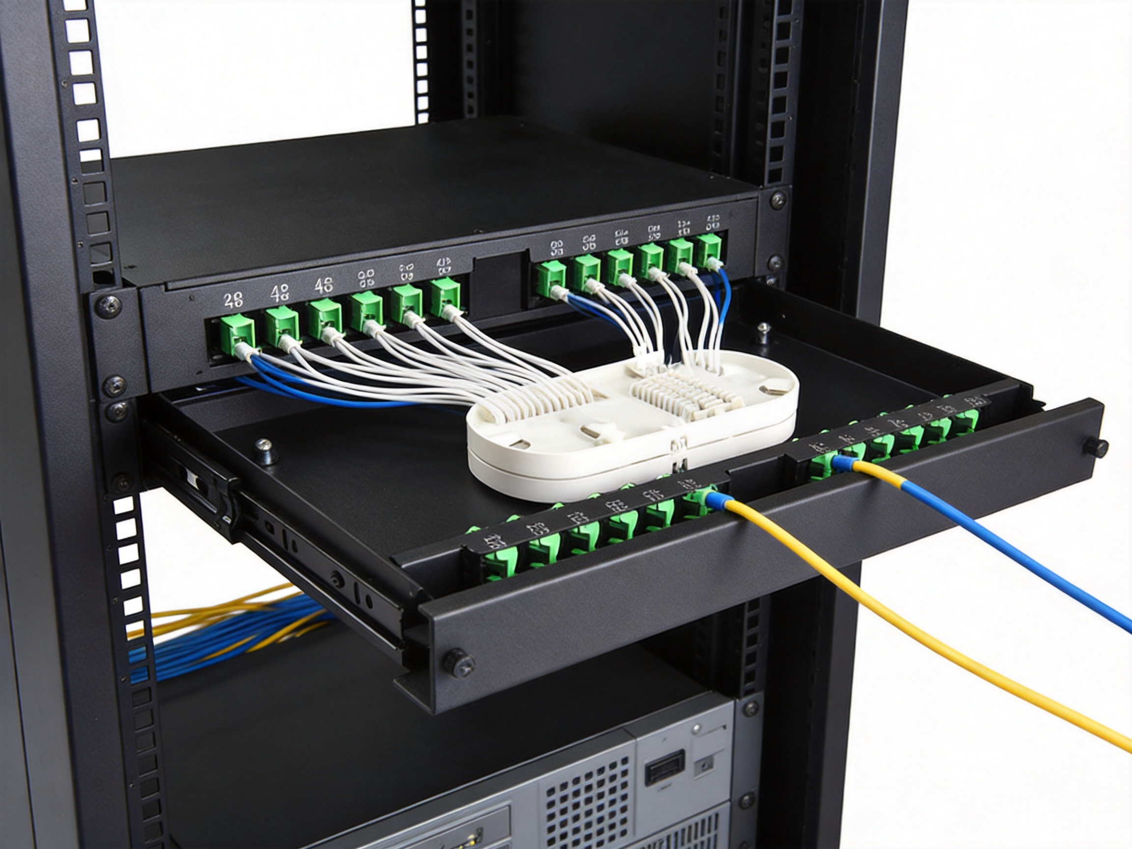
One of the most important practical features of the panel is its sliding structure. Conventional fixed enclosures can require technicians to work through a restricted front opening or remove the entire panel from the rack when they need to reach internal components. A sliding tray or sliding chassis can reduce this inconvenience by bringing the working area forward while the main enclosure remains mounted.
Improved access has direct operational benefits. During installation, technicians can inspect fiber routing more easily, position pigtails with less obstruction, and verify connector seating before closing the enclosure. During maintenance, the sliding mechanism can make it easier to trace individual fibers, check adapter positions, replace patch cords, and examine splice or storage areas. This can reduce the time spent working in a crowded equipment cabinet.
Fiber is sensitive to excessive bending, pulling, twisting, and repeated movement. A well-managed sliding structure enables technicians to access the service area without unnecessarily disturbing neighboring equipment or permanently routed cables. The enclosure can help separate working movements from fixed cable routes, reducing the likelihood of accidental strain on terminations.
The sliding design also supports a more efficient workflow during network expansion. When new fibers are added, a technician can access the relevant section, perform the required connection work, update labels, and return the tray to its operating position. This is more practical than treating the complete cabinet as a disassembly project each time a minor change is required.
For maintenance departments, accessibility can influence the total cost of ownership. A panel that saves time during every inspection or service activity may provide value throughout the life of the network. The benefit is especially significant in facilities where access windows are limited, service interruptions are expensive, or multiple systems share the same rack.
High-Density 48-Port Organization in a 2U Space
Rack space is a valuable resource in data centers, telecommunications rooms, and enterprise equipment rooms. High-density patching allows more connections to be managed without continuously increasing cabinet size or adding additional racks. The 48-port capacity of this panel is intended for projects that need substantial fiber termination within a compact footprint.
High density, however, must be combined with practical organization. A panel should not merely fit a large number of adapters into a small enclosure; it should also provide a layout that allows ports to be identified, accessed, and maintained. The value of the SMT-2206-48P-2U is therefore associated with the combination of port capacity, 2U rack utilization, and sliding access.
Consolidating fiber connections into a dedicated panel helps reduce scattered terminations throughout the cabinet. It can make patching routes easier to understand and support more consistent documentation. Port labels, cable identifiers, and rack elevation records can be coordinated around a central connection point. This creates a cleaner administration structure for installers and network operators.
High-density deployment is also useful where the number of incoming backbone fibers is growing but the available rack area is fixed. A 48-port panel may help project planners avoid using several lower-capacity enclosures for the same group of connections. Fewer enclosures can simplify cabinet layout, reduce the number of separate mounting operations, and make future inspection more straightforward.
At the same time, high-density installations must be planned carefully. Patch cords should be selected at suitable lengths, routed without sharp bends, and labeled consistently. Technicians should avoid overfilling cable pathways or applying pressure to connector bodies. The panel provides the structural foundation for organized fiber management, but good installation practice remains essential to achieving reliable performance.
SC-LC Connectivity for Flexible Network Design
Fiber networks may contain more than one connector format because of equipment changes, legacy infrastructure, different installation phases, or project-specific requirements. SC and LC connectors are both widely recognized in fiber communication systems, but they serve different practical preferences. SC connectors offer a larger push-pull interface that many technicians find simple to handle, while LC connectors provide a compact form factor that supports higher density at equipment interfaces.
A panel configured for SC-LC applications can help bridge these requirements within a structured connection environment. It may be used to organize SC-side backbone terminations and LC-side equipment patching, or it may be configured according to the connector arrangement specified by the customer. The result is a more adaptable interface between the permanent fiber plant and the active network layer.
Connector selection should always correspond to the fiber type, transceiver interface, optical budget, and installation standard of the project. The panel itself does not replace proper connector inspection and cleaning. Every adapter and patch cord should be handled according to accepted fiber installation procedures. Dust caps should remain in place on unused ports, and connectors should be inspected before mating.
For system integrators, SC-LC support can reduce the need to design a completely new enclosure for every network variation. A suitable patch panel platform can be incorporated into telecommunications rooms, campus networks, fiber-to-the-building installations, security backbones, and equipment cabinets where connector compatibility is a central planning issue.
Protection and Fiber Management
Fiber terminations require protection from physical damage, contamination, uncontrolled bending, and accidental pulling. A rack-mounted patch panel creates an enclosure around the termination area and helps keep connections away from casual contact. It also provides a defined routing environment for pigtails and patch cords.
Good fiber management should preserve the recommended bend radius of the fiber and avoid sharp transitions. The panel’s internal organization is intended to help installers guide fibers in a controlled manner rather than leaving loose loops or unsupported cables inside the cabinet. Proper routing reduces mechanical stress and makes future tracing easier.
The enclosure can also help protect connections from the general activity of an equipment room. Technicians may need to access switches, power distribution units, copper panels, or other hardware within the same cabinet. A dedicated optical patching area reduces the chance that routine work on adjacent equipment will disturb fiber terminations.
Protection is not limited to physical shielding. Clear port identification and logical cable arrangement also protect the network against human error. When a technician can quickly identify the correct port and follow a predictable routing pattern, the risk of disconnecting an active service or patching the wrong circuit is reduced.
For best results, the panel should be used with suitable rack hardware, compatible adapters, correctly sized patch cords, and a documented labeling plan. Installation teams should also maintain adequate slack management without creating excessive loops. The goal is a balance between serviceability and controlled fiber routing.
Installation and Maintenance Efficiency
Installation efficiency affects project schedules, labor costs, and commissioning quality. A rack-mount enclosure with an accessible sliding working area can simplify several stages of deployment. The technician can prepare the panel, arrange fiber connections, verify port numbering, and complete testing in a defined work zone.
During the initial installation, the panel can serve as a central reference point for backbone fibers. Incoming cables can be routed into the rack, terminated according to the selected configuration, and organized within the enclosure. Patch cords can then be connected to network equipment using a planned route. This separation helps prevent the patching area from becoming a random collection of crossing cables.
During testing and commissioning, accessibility can support visual inspection and measurement activities. Technicians may need to check polarity, verify continuity, inspect connector end faces, or measure optical loss. A panel that allows easier access can reduce the number of movements required to complete these tasks. Test results can then be recorded against the corresponding port numbers.
During service, the sliding structure can help maintenance personnel identify a connection without removing unrelated equipment. This is valuable in operational networks where even small interventions must be completed carefully. The ability to inspect the working area while the panel remains mounted can also support more controlled troubleshooting.
Clear documentation should accompany the physical installation. A recommended record may include rack number, panel identification, port number, cable origin, cable destination, fiber type, connector type, service status, installation date, and test result. The panel provides the physical organization needed to make such documentation useful and sustainable.

Benefits Compared with Basic Fixed Patch Panels
Basic fixed patch panels can be suitable for small installations or locations where access requirements are limited. However, they may become less convenient as port density, service complexity, and maintenance frequency increase. The sliding 2U design offers several advantages in comparison with a simple fixed enclosure.
First, service access is improved. A fixed panel may force the technician to reach through a narrow front area or work around patch cords that obstruct the internal components. A sliding arrangement can present the working area more directly and reduce unnecessary interference with adjacent connections.
Second, the high-capacity 48-port layout can provide more connection capacity per enclosure than smaller patching solutions. This can help reduce the number of panels required for a given fiber count and support a more compact rack plan.
Third, the combination of SC-LC compatibility and organized rack mounting can provide greater flexibility than a basic single-format solution. This is useful for projects that connect different network generations or equipment interface types.
Fourth, the enclosure supports a more professional administration model. Centralized fiber termination, consistent labeling, and controlled patching routes can improve the appearance and usability of the rack. A neat cabinet is not only visually preferable; it also makes troubleshooting, auditing, and future changes more predictable.
Finally, a sliding high-density panel can be advantageous in projects where labor efficiency is important. The initial product cost is only one part of the total investment. Installation time, maintenance time, service disruption, and future expansion effort should also be considered when comparing patching solutions.
Advantages Over Inadequately Designed High-Density Products
High port density alone does not guarantee a good fiber management solution. Some compact products may prioritize the number of adapters while providing limited working space, poor access, or insufficient attention to routing. Such limitations can cause difficulty during termination and increase the possibility of fiber stress.
The SMT-2206-48P-2U addresses the practical side of density by combining a substantial port count with a sliding access concept. This approach is intended to make the dense connection area more manageable rather than simply more crowded. For installers, the benefit is a working environment that can be accessed and organized more deliberately.
A professional patch panel should also be evaluated for manufacturing consistency. Adapter alignment, panel fit, moving-part operation, mounting accuracy, and surface quality influence the installation experience. When these elements are produced under controlled processes, the product is more likely to perform consistently across larger quantities.
Customization is another area where a specialized manufacturer can offer an advantage. Projects may require different labeling formats, adapter arrangements, fiber counts, colors, packaging, or private-label identification. A supplier with design and production capabilities can coordinate these requirements more effectively than a general reseller with limited control over the manufacturing process.
Manufacturing Strengths of the Supplier
Yuyao Simante Network Communication Equipment Co., Ltd. is a professional manufacturer of network cabling solutions and optical fiber products. The company integrates design, development, sales, and service, allowing customer requirements to be considered across the product life cycle rather than only at the final sales stage.
The company reports nearly 20 years of service experience in the network communication field. This period of operation provides practical exposure to changing cabling standards, installation conditions, customer expectations, and international market requirements. Long-term experience can be particularly valuable for products such as patch panels, where small design details influence installation efficiency and field reliability.
According to the supplied company information, the manufacturer has more than 10 engineers and over 30 full-time technical personnel. This technical team supports product development, quality improvement, production coordination, and product updates. Engineering resources are important when customers require more than a standard catalog item, especially for OEM and ODM projects.
The company also states that it operates 10 regular and customization production lines. This production structure supports both standard product supply and project-specific requirements. Customization lines can be useful when a buyer needs a particular housing design, port arrangement, marking method, packaging format, or product identity.
Its reported equipment includes 10 fully automatic injection molding machines, 20 semi-automatic injection molding machines, and eight automatic assembly machines. These resources indicate an emphasis on repeatable manufacturing and production efficiency. Automated or semi-automated equipment can help control important process variables, improve output consistency, and reduce variation caused by purely manual operations.
The reported annual output exceeds 9 million units across the company’s product range. A production capacity of this scale can support ongoing supply programs, distributor orders, and larger structured cabling projects. It also suggests that the manufacturer has established procedures for material management, production scheduling, inspection, packaging, and shipment coordination.
Design Quality from the Source
Product quality begins before assembly. Decisions regarding enclosure geometry, mounting points, moving components, adapter placement, cable entry, labeling, and internal management influence how well the final product serves installers. A mature research and development system can identify potential problems at the design stage instead of relying exclusively on end-of-line inspection.
The supplier emphasizes that its research and development system helps guarantee product stability from the design source. For the SMT-2206-48P-2U, this principle is relevant to the relationship between the 2U housing, 48-port arrangement, and sliding access mechanism. These features must work together so that the panel is dense without becoming difficult to service.
Design review should consider repeated opening and closing, rack mounting, patch cord movement, adapter alignment, fiber routing, and maintenance access. It should also consider the practical environment in which the product will be used. Telecommunications rooms may have limited working space, while data centers may require careful cable identification and rapid service restoration. A product designed with these conditions in mind can provide greater value than one designed only around appearance or nominal capacity.
The supplier’s combined engineering and manufacturing structure allows design feedback to move more quickly into production improvements. If installers identify a difficulty with labeling, access, assembly, or packaging, an integrated manufacturer is better positioned to review the issue and implement a controlled update.
Quality Control and Performance Testing
Fiber connectivity products must be manufactured with attention to dimensional accuracy, component fit, material quality, assembly consistency, and cleanliness. Even when a patch panel is passive, defects in alignment or assembly can affect installation quality and long-term usability.
The company states that it uses performance testing to meet comprehensive customer requirements. Testing may be organized around the characteristics specified for each product and customer order. For a fiber optical patch panel, relevant inspection areas can include enclosure appearance, mounting dimensions, port identification, adapter fit, sliding operation, assembly security, and compatibility with the selected fiber components.
Where fiber assemblies or adapters are supplied as part of a configured product, the buyer should confirm the applicable optical and mechanical test records. Depending on the project, these may include insertion loss, return loss, polarity, end-face inspection, continuity, and environmental or mechanical requirements. The exact test scope should be agreed during technical review because requirements vary according to the application and applicable standards.
Quality control is most effective when it is applied throughout production. Incoming material inspection helps control the quality of plastics, metal parts, adapters, labels, and other components. Process inspection helps verify assembly steps. Final inspection confirms that the completed product corresponds with the order configuration before packaging.
Consistent inspection also supports repeat orders. Network operators and distributors often need products that match previous deliveries in appearance, fit, labeling, and function. Stable manufacturing processes reduce the risk of unexpected differences between batches.
OEM and ODM Project Support
Structured cabling projects are not always based on a single universal specification. A contractor may require private labeling, while a distributor may need retail packaging and a specific product code. An international system integrator may request a customized port layout or a panel adapted to an existing product family.
The supplier’s OEM and ODM capability is therefore an important commercial advantage. OEM production can support customers that want products manufactured under their own brand or project identity. ODM cooperation can support customers that need a product developed or modified around particular installation requirements.
Customization should be managed through a formal technical process. The buyer and manufacturer should confirm drawings, materials, port count, connector format, labeling, color, packaging, inspection criteria, and order quantities before production. Samples or first-article approvals may also be appropriate for customized designs.
For the SMT-2206-48P-2U, customization possibilities may include adapter configuration, port numbering, identification labels, fiber management accessories, packaging, and external markings, subject to engineering review. These options allow the panel to be incorporated more smoothly into a customer’s existing structured cabling system.
Applications in Different Network Environments
Data Centers
Data centers require high-density connections, clear rack organization, and efficient change management. The 48-port 2U format can help consolidate fiber connections within a defined rack location. The sliding design supports maintenance in cabinets where equipment density makes front access particularly important.
Data center operators can use the panel for connections between backbone cabling, fiber distribution areas, switches, storage systems, and cross-connect zones. Detailed port labeling and documentation are essential because data center changes may be frequent and service impact must be minimized.
Telecommunications Rooms
Telecommunications rooms often serve as distribution points for buildings, campuses, or regional facilities. They may contain backbone fiber arriving from different areas and connections leaving toward access switches or intermediate distribution points. A rack-mounted optical patch panel provides a central location for these links.
The panel can help telecommunications technicians organize connections by floor, building, service, or cable route. Its high capacity is useful where many fibers converge in a limited room or cabinet space.
Enterprise Networks
Large offices, hospitals, universities, financial institutions, and manufacturing companies increasingly use fiber for backbone links, server rooms, surveillance systems, and high-bandwidth applications. A structured patching enclosure helps these organizations manage fiber connections separately from active equipment and makes future changes more orderly.
Security and Surveillance Systems
Video surveillance networks may use fiber to connect cameras, remote buildings, control rooms, and recording facilities. The patch panel can provide a central termination point for these links. Clear identification is especially important when different security zones or remote locations are connected to the same rack.
Industrial and Building Automation Networks
Industrial sites and smart buildings may require fiber connections between control cabinets, network rooms, production areas, and monitoring systems. Fiber can provide communication over longer distances and can help separate network links from electromagnetic interference sources. A rack-mounted panel offers an organized interface for these connections, subject to the environmental requirements of the installation location.
Network Integration Projects
System integrators can use the panel as part of complete copper and fiber structured cabling solutions. The manufacturer’s broader product range includes keystone jacks, patch panels, wall face plates, data sockets, and related network cabling products. This product breadth can help integrators coordinate multiple components through one experienced supplier.
Recommended Installation Practices
Before installation, confirm rack compatibility, available 2U space, connector configuration, port numbering, cable entry direction, and the required fiber management method. Review the project drawings and ensure that the panel location allows the sliding mechanism to operate without obstruction.
Install the enclosure securely using suitable rack hardware. The panel should be supported evenly and aligned with neighboring equipment. Avoid forcing the chassis into a rack position if the mounting holes are not aligned, because mechanical stress can affect the enclosure or rack threads.
Route incoming cables so that they are supported before they enter the panel. The cable jacket, strength members, and strain-relief arrangement should be handled according to the cable manufacturer’s instructions. Avoid allowing the weight of a long cable to be transferred directly to the fiber terminations.
Maintain the recommended bend radius throughout the installation. Do not create tight loops behind the panel or use excessive cable ties. Hook-and-loop fasteners are often preferable to overly tight permanent ties because they allow future adjustment without compressing the cable.
Clean and inspect connectors before connection. Dust, oil, or debris on an end face can increase optical loss or damage mating surfaces. Unused adapters and connectors should be protected with suitable caps.
Apply labels before the rack becomes crowded. Each port should be identified according to the project’s documentation system, and both ends of each fiber link should have matching or traceable identifiers. Labels should remain readable after installation and should not interfere with the sliding mechanism.
After patching, check that the tray or sliding section moves smoothly and returns to its intended position without trapping or sharply bending patch cords. Complete optical testing and record the results against the correct port numbers.
How to Select the Correct Configuration
The appropriate panel configuration depends on more than the number of ports. Project planners should first determine the fiber count, connector type, fiber mode, polarity method, termination method, and rack requirements. They should also consider whether the panel will be used for direct patching, splice management, pre-terminated assemblies, or a combination of these functions.
For a 48-port application, confirm whether “48 ports” refers to individual adapter positions, duplex connector positions, or another project-specific counting method. Connector terminology can differ between suppliers, and confirming the physical port arrangement prevents ordering errors.
Next, verify the SC-LC arrangement. Some projects may require SC adapters on one side and LC interfaces on the other, while others may need a particular adapter plate or mixed configuration. The exact arrangement should be shown on a technical drawing or written specification.
Rack depth and front clearance should also be checked. A sliding panel needs sufficient space in front of the cabinet for the tray or chassis to move forward. Adjacent doors, cable managers, vertical posts, and other equipment should not block its operation.
Finally, confirm the required accessories and documentation. Buyers may need pigtails, splice trays, adapter plates, labels, mounting hardware, dust caps, test reports, packaging specifications, or spare components. Early confirmation helps the manufacturer supply a complete and compatible solution.
Why Manufacturer Experience Matters
A fiber patch panel may appear simple from the outside, but its usefulness depends on many details that affect field work. Manufacturing experience helps a supplier understand the relationship between product design, installation practice, production repeatability, and customer support.
Yuyao Simante Network Communication Equipment Co., Ltd. has developed its business around network cabling solutions and optical fiber products. Its experience covers both standard products and customized supply. This combination is valuable for customers that need dependable catalog items as well as those developing a broader structured cabling program.
The company’s engineering team, production lines, automatic equipment, and reported annual output provide a foundation for serving different order sizes. A small integrator may need a standard batch, while a distributor or major project may require recurring deliveries and consistent packaging. A manufacturer with established capacity can plan these requirements more effectively.
International market experience is also relevant. The company reports stable export activity in Europe, Australia, Africa, the Middle East, and Southeast Asia. Serving different regions requires attention to communication, packaging, documentation, product adaptation, and delivery coordination. This international exposure can help customers manage cross-border sourcing for structured cabling products.
Purchasing and Project Planning Considerations
When purchasing the SMT-2206-48P-2U, customers should provide a clear technical brief. The brief should identify the expected quantity, delivery schedule, connector configuration, port numbering, labeling requirements, packaging needs, and any applicable quality or testing requirements.
For a project involving multiple racks, it is useful to provide a rack elevation or connection schedule. This allows the supplier to confirm whether the selected configuration matches the intended installation. If a customized version is required, drawings should be reviewed before mass production.
Buyers should also ask for sample approval when the panel is part of a new product family or a complex installation. A sample can be used to evaluate rack fit, sliding action, port labeling, patch cord routing, and overall workmanship. Approval criteria should be recorded so that production can be checked against the accepted sample.
Packaging is important for fiber products because connectors, adapters, labels, and moving parts must be protected during transportation. The packaging specification should account for the shipping method, handling conditions, stacking, moisture exposure, and the need to keep optical interfaces clean.
After delivery, inspect the shipment promptly. Check quantities, external condition, product codes, port configuration, accessories, and documentation. Any discrepancy should be reported with photographs, batch information, and purchase order details so that corrective action can be taken efficiently.
Operational Value Over the Product Life Cycle
The value of a fiber patch panel should be evaluated over the entire life of the network. During installation, it saves time by organizing terminations and providing an accessible work area. During operation, it creates a clear cross-connect point. During maintenance, it supports inspection and controlled changes. During expansion, it provides a structured location for additional patching activity.
A well-managed panel can also extend the practical usability of a rack. When fiber routes remain organized, new equipment can be added with less disruption. When port records are accurate, technicians can identify available capacity more quickly. When connections are protected and labeled, troubleshooting becomes less dependent on individual installer knowledge.
The sliding design is especially valuable in environments where changes are expected. Networks in data centers, campuses, and commercial buildings are rarely static. Services are added, relocated, upgraded, or removed over time. Easy access helps the panel remain useful as the network evolves.
The 2U form factor also contributes to long-term planning. It offers a defined rack-space requirement that can be included in cabinet layouts and capacity forecasts. A 48-port configuration provides a substantial connection reserve for many installations while maintaining a manageable enclosure footprint.
Q&A
What is the SMT-2206-48P-2U?
It is a 2U sliding type rack-mount fiber optical patch panel designed for organized fiber termination and cross-connection. The stated configuration provides 48 ports and supports SC-LC fiber connection arrangements.
What does the 2U designation mean?
2U describes the vertical rack space occupied by the enclosure in a standard equipment rack. The exact installation depth and clearance should be confirmed from the technical drawing for the selected configuration.
What is the advantage of a sliding patch panel?
A sliding structure brings the working area forward for installation, inspection, patching, and maintenance. It can reduce the need to remove the panel from the rack and can make dense fiber connections easier to access.
Is the panel suitable for both SC and LC connectors?
The product is identified as an SC-LC rack-mount fiber optical patch panel. The exact adapter arrangement should be confirmed before ordering because projects may require different SC and LC positions, adapter types, or termination configurations.
Does the panel include fiber pigtails or splice accessories?
The supplied product information identifies the patch panel but does not specify every accessory or internal configuration. Buyers should confirm whether pigtails, splice trays, adapters, labels, mounting hardware, or other components are included in the quotation.
Where can this product be used?
Typical applications include data centers, telecommunications rooms, enterprise networks, security backbones, smart buildings, industrial communication systems, and other structured fiber cabling installations.
How should the panel be maintained?
Maintenance should include connector inspection and cleaning, label verification, patch cord examination, bend-radius checks, sliding-mechanism inspection, and updated connection documentation. Unused optical interfaces should remain capped and protected.
Can the product be customized?
The manufacturer undertakes OEM and ODM projects and operates regular and customization production lines. Possible customization requirements should be discussed with the engineering team and confirmed through drawings, samples, and written specifications.
What manufacturing capabilities support this product?
The company reports more than 10 engineers, over 30 full-time technical personnel, 10 regular and customization production lines, 10 fully automatic injection molding machines, 20 semi-automatic injection molding machines, and eight automatic assembly machines. It also reports annual production exceeding 9 million units across its product range.
What should be confirmed before placing an order?
Confirm port count interpretation, SC-LC arrangement, fiber mode, adapter and pigtail requirements, rack dimensions, sliding clearance, labeling, accessories, testing, packaging, quantity, delivery schedule, and any OEM or ODM requirements.
Conclusion
The SMT-2206-48P-2U Sliding Type SC-LC Rack Mount Fiber Optical Patch Panel 2U provides a practical combination of density, accessibility, and structured fiber management. Its 48-port capacity helps consolidate connections within a 2U rack space, while the sliding design improves access for installation and maintenance. Support for SC-LC configurations makes it suitable for a variety of network architectures in which different connector formats or equipment interfaces must be organized efficiently.
Compared with basic fixed or poorly organized high-density solutions, the panel offers a more serviceable approach to rack-based fiber administration. Its value is not limited to the number of ports. The combination of accessible construction, protected termination space, organized patching, and professional rack integration can reduce installation effort and improve long-term network manageability.
The manufacturing capabilities of Yuyao Simante Network Communication Equipment Co., Ltd. further strengthen the product proposition. The company combines design, development, production, testing, sales, and service; maintains engineering and technical teams; operates standard and customized production lines; and supports OEM and ODM cooperation. Its reported manufacturing equipment, production capacity, export experience, and emphasis on performance testing provide a foundation for supplying both standard and project-specific structured cabling solutions.
For organizations planning a new fiber network or upgrading an existing rack system, the panel should be evaluated together with the complete connection design. When correctly configured, installed, labeled, and tested, it can serve as a dependable central interface for high-density fiber connections and contribute to a cleaner, more maintainable, and more scalable structured cabling infrastructure.
References
1. Product information supplied for the SMT-2206-48P-2U Sliding Type SC-LC Rack Mount Fiber Optical Patch Panel 2U.
2. Company profile and manufacturing information supplied by Yuyao Simante Network Communication Equipment Co., Ltd.
3. General principles of fiber optic connector handling, cleaning, inspection, and cable management.
4. General structured cabling design practices for telecommunications rooms, data centers, and equipment racks.
5. General rack-unit planning and high-density fiber distribution considerations for communication infrastructure.