Español
 عربى
عربى русский
Content
- 1 Product Overview
- 2 Purpose in a Structured Cabling System
- 3 1U Rack-Mounted Design
- 4 Shielded Metal Construction
- 5 24-Port Capacity and Port Administration
- 6 Rear Cable Management
- 7 Electrical and Mechanical Performance
- 8 Advantages Compared with Basic Patch Panel Alternatives
- 9 Installation Recommendations
- 10 Applications
- 11 Quality and Manufacturing Strengths
- 12 Environmental Compliance and Operating Conditions
- 13 Packaging, Storage, and Logistics
- 14 Procurement Considerations for Distributors and Integrators
- 15 Recommended Maintenance Practices
- 16 Why Manufacturing Experience Matters
- 17 Q&A
- 17.1 What is the SMT-2016-24P-FTP?
- 17.2 Why is it called a blank patch panel?
- 17.3 How many ports does the panel provide?
- 17.4 Can it be installed in a standard network cabinet?
- 17.5 What is the advantage of the shielded design?
- 17.6 Does the product include cable management?
- 17.7 How are the ports identified?
- 17.8 What connectors should be used with this panel?
- 17.9 What are the electrical specifications?
- 17.10 What are the mechanical specifications?
- 17.11 What materials are used?
- 17.12 What are the environmental requirements?
- 17.13 How should the product be stored?
- 17.14 How is the product packaged?
- 17.15 Can customer-specific packaging be requested?
- 17.16 Does the manufacturer support OEM and ODM projects?
- 17.17 What other products does the manufacturer produce?
- 17.18 Why is port labeling important?
- 17.19 Why should the rear cable manager be used?
- 18 Conclusion
- 19 References
- 20 Product: SMT-2016-24P-FTP 1U24 Port Shielded Blank Patch Panel
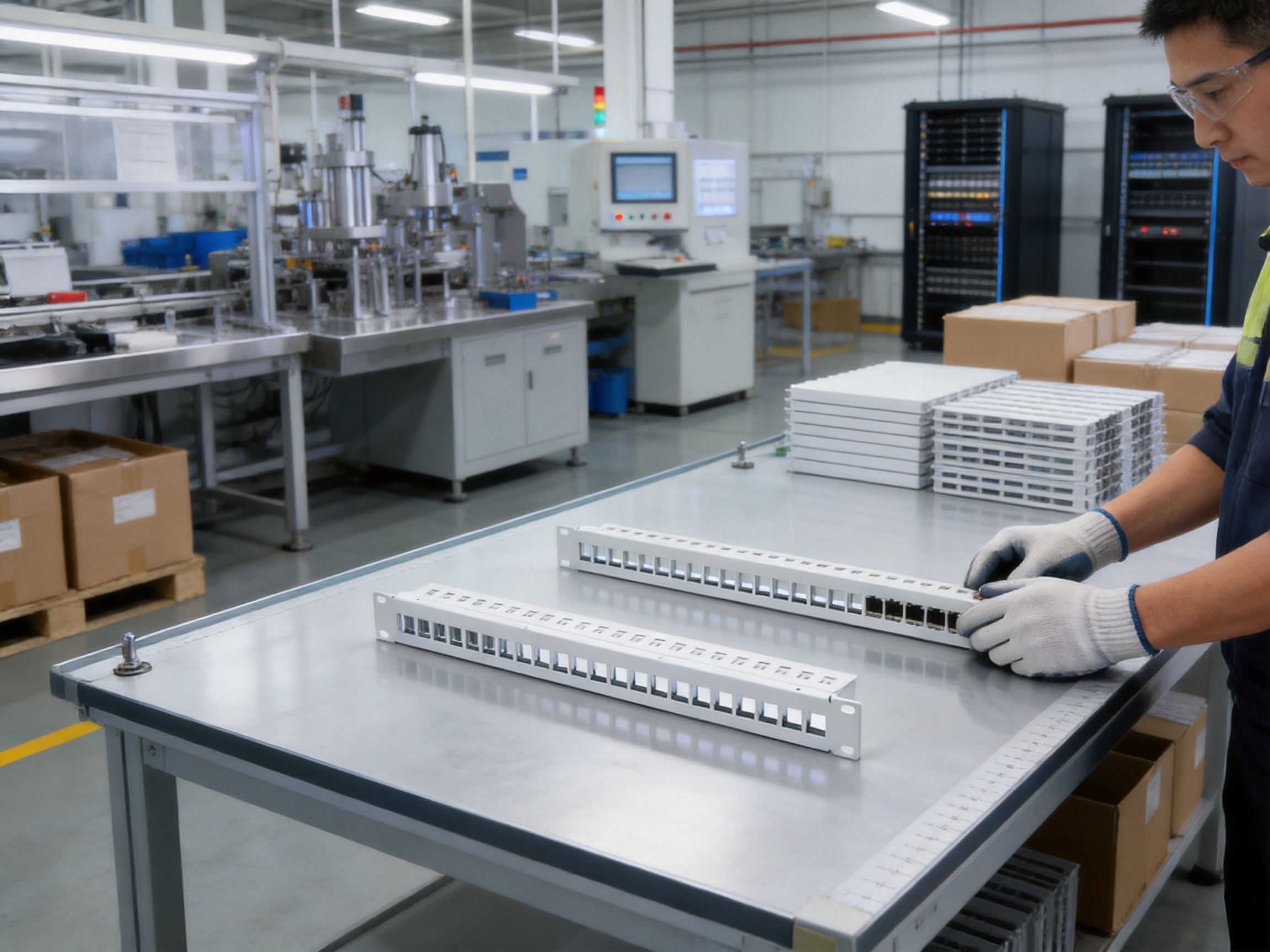
Modern communication networks depend on orderly, reliable, and serviceable cabling infrastructure. Whether installed in an enterprise data room, telecommunications cabinet, commercial building, industrial facility, smart-home project, or equipment room, the patch panel is an essential part of the structured cabling system. It provides a central point where horizontal cables, equipment connections, and termination points can be organized, identified, maintained, and managed.
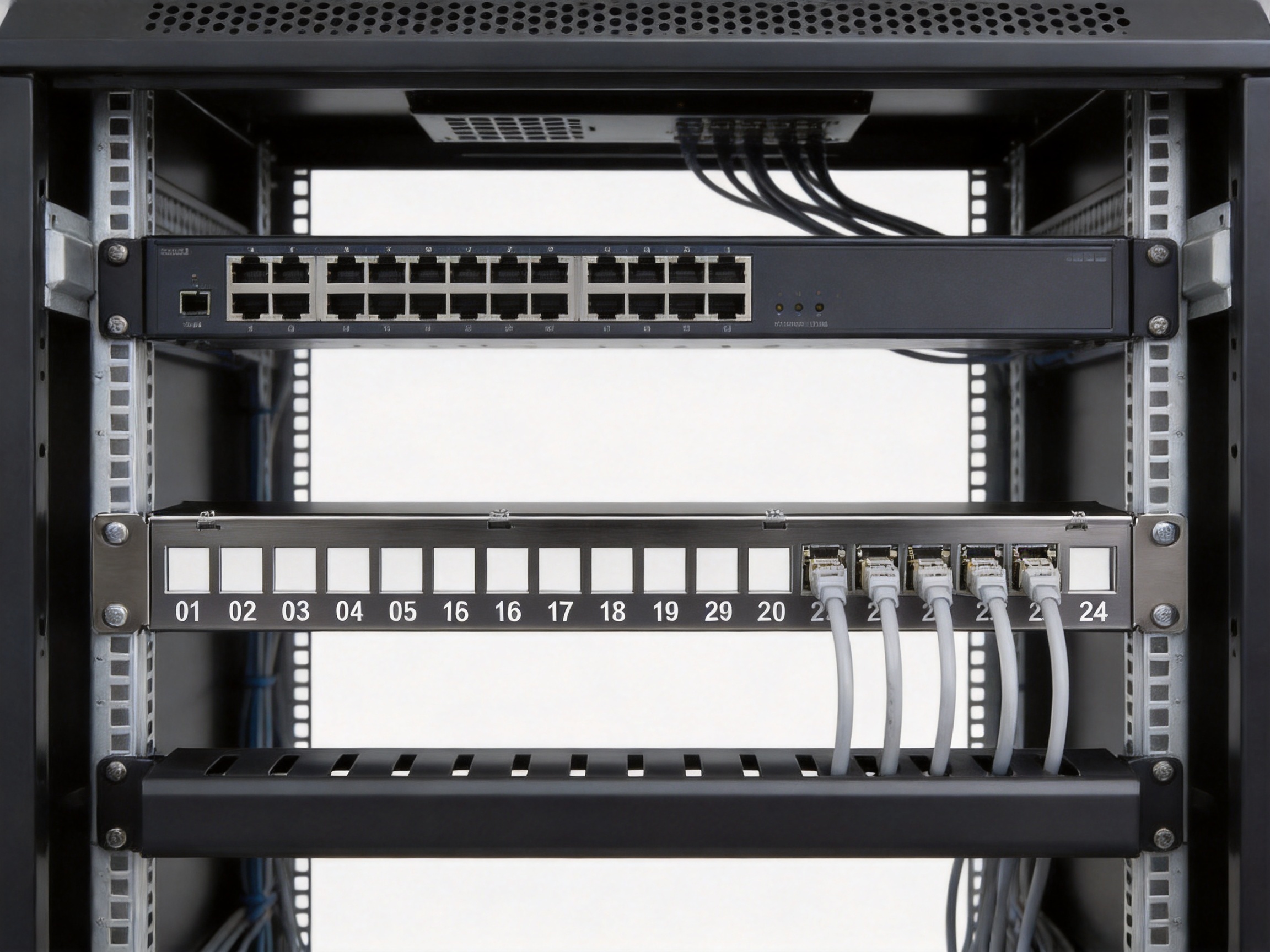
The SMT-2016-24P-FTP 1U 24-Port Shielded Blank Patch Panel is designed for this purpose. It is a 19-inch rack-mounted blank patch panel with 24 shielded port positions, a sturdy metal structure, front identification labels, rear cable management, and a convenient grounding fixture. The product is suitable for horizontal wiring, device termination, and centralized mutual mating termination between compatible connectors of the same standard series.
Its design combines installation efficiency, mechanical stability, identification convenience, grounding capability, and long-term serviceability. Compared with basic unshielded or poorly organized blank panels, this model provides a more professional platform for structured cabling projects that require reliable cable routing, clear port administration, and compatibility with standard cabinets and racks.
Product Overview
The SMT-2016-24P-FTP is configured in a compact 1U format and provides 24 front-facing port positions. The standard 19-inch width allows the panel to be installed in common network racks, equipment cabinets, and compatible wall-mounted brackets. Its blank design allows installers and system integrators to select suitable connectors from the same standard series, making the panel adaptable to different copper and structured cabling requirements.
The panel is particularly suitable for applications where cable termination must be centralized and arranged in a clearly accessible location. Rather than allowing multiple cables to be terminated loosely inside a cabinet or distributed across different mounting points, the panel creates a neat and recognizable interface. This helps technicians identify ports, trace cable routes, perform maintenance, and expand the system in a controlled manner.
The shielded construction is appropriate for installations where additional electromagnetic protection and grounding continuity are important considerations. The rear grounding fixture allows the metal panel to be connected conveniently and effectively to the grounding system. Proper grounding should always be completed in accordance with the applicable electrical and installation standards for the project.
| Item | Specification |
|---|---|
| Product model | SMT-2016-24P-FTP |
| Product type | 1U 24-port shielded blank patch panel |
| Mounting format | 19-inch rack-mounted standard |
| Port quantity | 24 |
| Primary application | Horizontal wiring, device termination, and centralized termination |
| Front identification | Individual port labels and large front labeling area |
| Rear structure | Cable manager and grounding fixture |
| Metal material | Cold-rolled steel |
| Surface treatment | Sprayed and nickel-plated treatment |
| Insulation resistance | Initial value of at least 1000 MΩ |
| Insertion force | Not more than 12 N |
| Pull-out force | Not less than 20 N |
| Operating temperature range | -25°C to +70°C |
| Environmental compliance | RoHS requirements |
Purpose in a Structured Cabling System
A structured cabling system is most effective when its permanent cables, equipment connections, and service interfaces are organized according to a consistent architecture. The patch panel is normally installed between field cabling and active network equipment, or between different sections of a structured cabling system. It provides a stable termination point and reduces the need to manipulate permanent cables whenever network equipment is replaced or rearranged.
The SMT-2016-24P-FTP can be used in horizontal cabling systems where cables run from work areas, outlets, or intermediate distribution points back to a communications cabinet. It can also be used for device termination or centralized connections where a clear and accessible port arrangement is required.
Because it is a blank patch panel, the installer can fit compatible modular connectors according to the project requirements. This allows the same chassis format to support different configurations within the relevant connector series. The product information specifies that it should be used with connectors of the same standard series. Following this matching requirement helps maintain proper mechanical fit, reliable retention, and appropriate electrical performance.
A well-organized patch panel contributes to a number of practical benefits:
• It separates permanent horizontal cabling from frequently changed equipment patch cords.
• It creates a visible and logical interface for port administration.
• It reduces cable stress by supporting controlled routing at the rear of the panel.
• It simplifies testing, troubleshooting, relocation, and future expansion.
• It improves the appearance and professional quality of the equipment cabinet.
• It supports more consistent installation practices across multiple projects.
1U Rack-Mounted Design
The 1U format is one of the most important practical advantages of the product. Rack space is valuable in modern communication rooms, especially where cabinets contain switches, routers, power distribution units, fiber enclosures, cable managers, and other network accessories. A compact 1U patch panel provides 24 port positions without occupying unnecessary vertical space.
Its 19-inch rack-mounted standard makes it suitable for common network cabinets and equipment racks. It can also be installed on compatible wall brackets where the project requires a smaller or wall-mounted distribution point. Standardized mounting dimensions make planning easier for installers and reduce the need for special mounting hardware or customized cabinet structures.
The sturdy construction supports stable installation. A rigid panel is less likely to flex during connector insertion, cable termination, or service work. This is important because excessive movement can make installation more difficult and may place unnecessary stress on the connectors or the rack mounting points.
The 1U structure also helps maintain a clean cabinet layout. By placing 24 ports in a single horizontal row, technicians can quickly understand the relationship between port numbers, patch cords, and connected equipment. When combined with appropriate vertical and horizontal cable management, the panel contributes to improved airflow and easier access to adjacent equipment.
Shielded Metal Construction
The panel uses a cold-rolled steel bracket with sprayed and nickel-plated surface treatment. Cold-rolled steel provides a solid base for a rack-mounted product and offers the rigidity needed for repeated installation and maintenance operations. The surface treatment contributes to appearance, corrosion resistance, and protection of the metal during normal handling and storage.
The shielded metal structure is an important distinction between this product and simpler non-metallic or unshielded alternatives. Shielding is not a substitute for correct system design, cable selection, connector compatibility, or grounding. However, when used as part of a properly designed shielded cabling system, the metal panel can help support the continuity of the shielding path and provide a suitable grounding point.
The rear grounding fixture is designed to make grounding convenient and effective. During installation, the grounding connection should be made securely and checked according to the requirements of the site and the relevant standards. A correctly grounded panel can contribute to a more consistent shielding architecture and helps ensure that the metal components of the installation are managed responsibly.
The metal bracket also gives the product a professional appearance. In commercial and industrial installations, physical presentation is not merely cosmetic. A neat and robust cabinet is easier to inspect, easier to document, and less likely to suffer accidental damage caused by loose cables or poorly supported components.
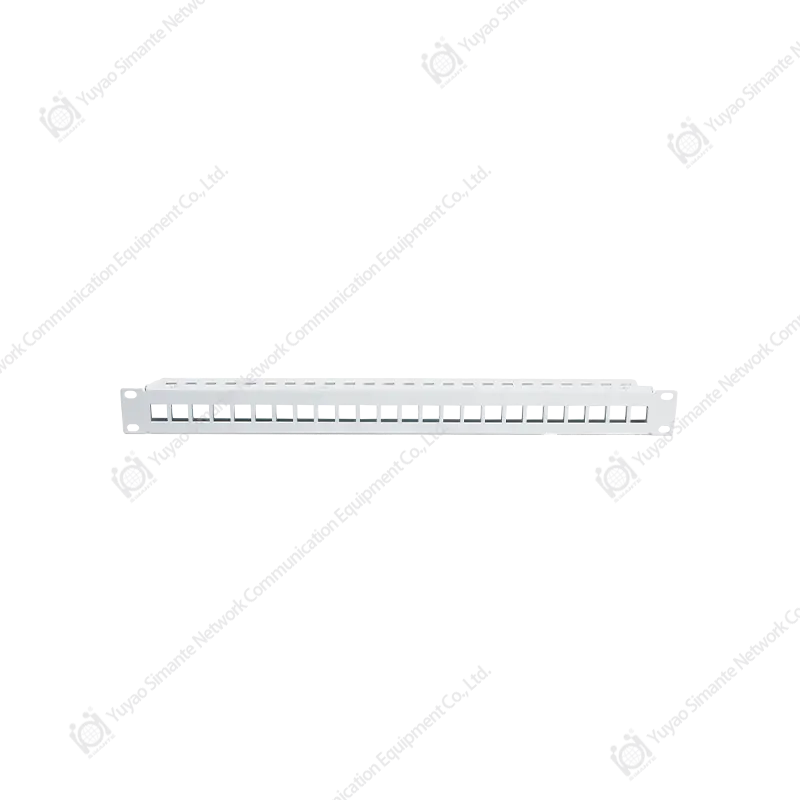
SMT-2016-24P-FTP 1U24 Port Shielded Blank Patch Panel
24-Port Capacity and Port Administration
Twenty-four ports provide a useful balance between density and accessibility. The panel offers enough capacity for many small and medium-sized cabinets while remaining compact enough for a 1U installation. It can serve a single work area distribution group, a small office floor, a security or automation network, or a dedicated equipment section within a larger structured cabling system.
Every port has front labeling, allowing the installer or network administrator to assign a clear identification scheme. Labels can be used for room numbers, outlet numbers, switch port references, cable identifiers, service types, or other project-specific information. Clear labeling reduces the time required to trace connections and can prevent errors during installation or maintenance.
In addition to individual port markings, the large front label area provides space for broader identification. This area can be used to indicate a cabinet number, distribution area, network segment, customer reference, or other information that helps technicians understand the role of the panel at a glance.
Effective labeling is one of the simplest ways to improve network administration. Without a consistent identification system, technicians may need to follow individual cables manually, interrupt active services, or rely on incomplete installation records. With visible labels, routine tasks such as moving a connection, testing a port, or investigating a fault can be completed more quickly and with less risk.
Rear Cable Management
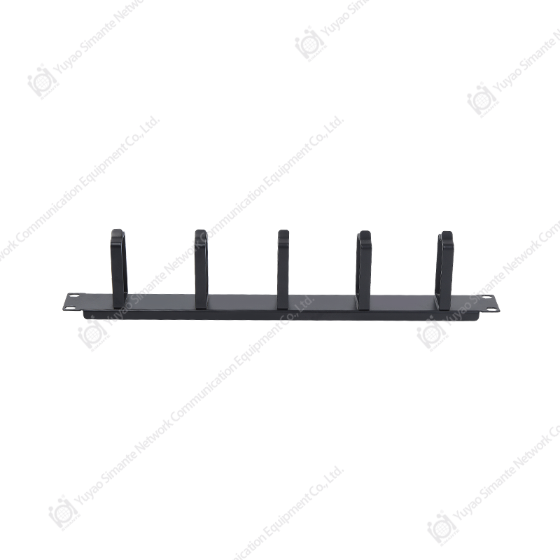
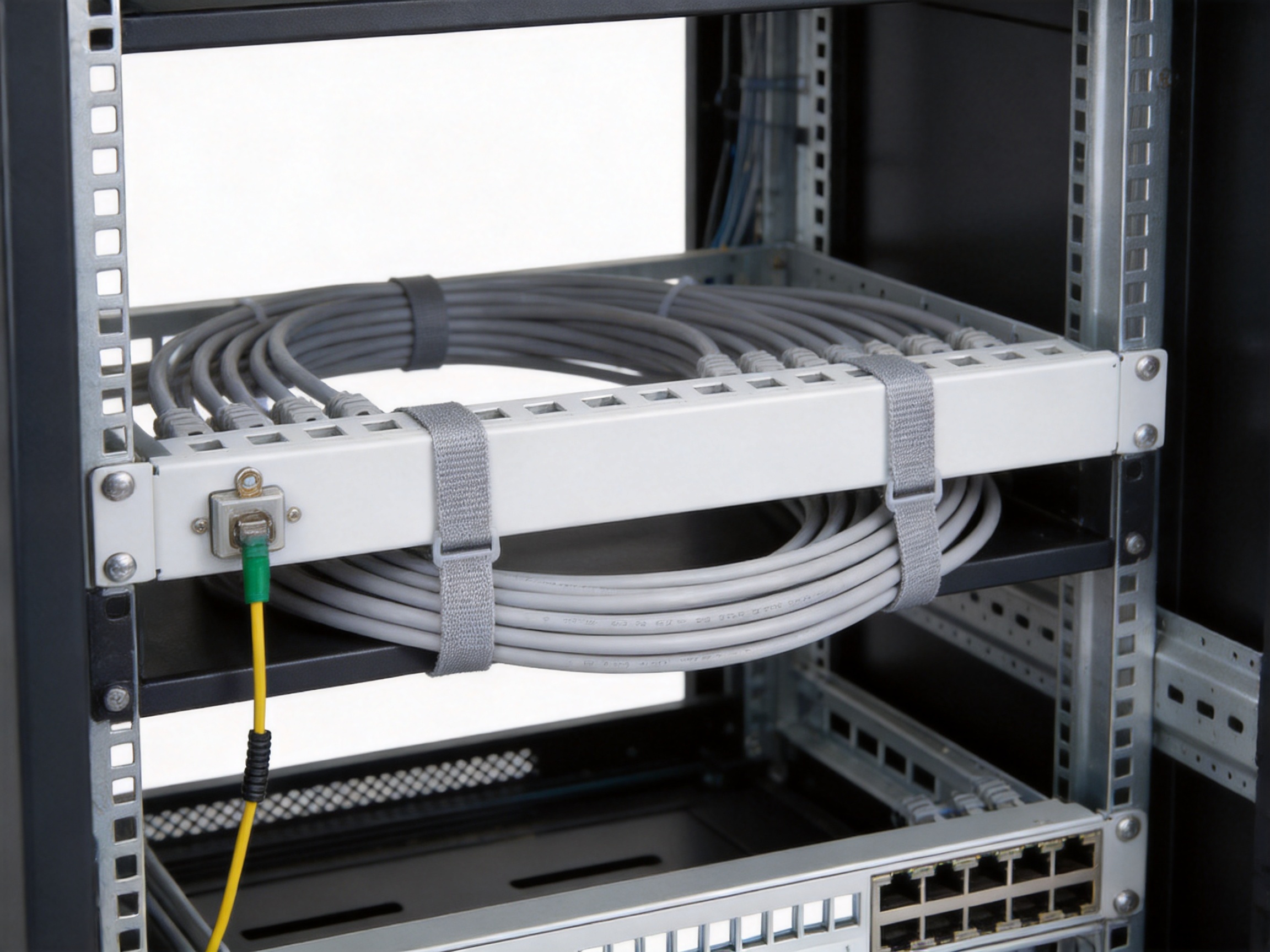
The rear-mounted cable manager is designed to guide cables toward their termination points. Cable management is a major factor in the long-term performance and maintainability of a structured cabling installation. Cables that are left unsupported or bent sharply can become difficult to identify and may experience unnecessary mechanical stress.
The cable manager helps organize the cable path behind the panel. It can support more consistent routing and increase the cable bend radius. Maintaining an appropriate bend radius is especially important for network cables and other structured cabling products because excessive bending may affect transmission performance, connector positioning, or long-term reliability.
A controlled cable path also improves the appearance and serviceability of the cabinet. When cables are arranged in a predictable pattern, technicians can more easily distinguish permanent cables from patch cords and can access the rear of the panel without disturbing unrelated connections.
Good cable management provides several additional advantages:
• It reduces the possibility of cables being pulled or twisted during service.
• It supports a more organized relationship between cable bundles and port numbers.
• It helps keep cable paths away from sharp edges and moving equipment.
• It makes future additions easier to plan and install.
• It supports a cleaner installation that is easier to inspect and document.
The cable manager should be used together with suitable cable ties, hook-and-loop straps, and installation practices that avoid over-compression. Cables should be supported without being crushed, and all routing work should follow the cable manufacturer’s recommendations.
Electrical and Mechanical Performance
Insulation Resistance
The product specification lists an initial insulation resistance of at least 1000 MΩ. Insulation resistance is an important electrical characteristic because it reflects the ability of insulating materials and separated conductive areas to resist unwanted current leakage. A high insulation resistance value supports electrical isolation under appropriate test conditions.
Actual system performance depends on the selected connectors, installed cables, termination quality, environmental conditions, and test method. For this reason, the patch panel should be installed with compatible components and tested as part of the completed cabling channel or link.
Insertion and Pull-Out Force
The specified insertion force is not more than 12 N, while the pull-out force is not less than 20 N. These values reflect the mechanical relationship between the panel and compatible connectors of the same standard series.
A controlled insertion force helps installers fit connectors without excessive effort. This can improve work efficiency when many ports must be populated. At the same time, adequate pull-out force helps prevent connectors from becoming loose during normal handling, cable routing, or routine maintenance.
These characteristics are particularly valuable in high-density installations. When a cabinet contains many connections, poor connector retention can lead to intermittent faults, accidental disconnections, and repeated service calls. Correct connector selection and complete engagement remain essential, but the panel’s mechanical design provides a stable foundation for the termination system.
Advantages Compared with Basic Patch Panel Alternatives
The SMT-2016-24P-FTP has several practical advantages over basic blank panels that provide only a flat mounting surface without integrated cable management, grounding provisions, or clear labeling support.
More Complete Installation Functionality
A basic panel may hold connectors in a rack, but it may not provide a rear cable manager or a convenient grounding fixture. This product combines these functions in one installation platform. As a result, the installer does not need to create as many improvised support arrangements behind the panel.
Improved Port Identification
Some low-cost panels offer limited labeling space or markings that are difficult to read after installation. The SMT-2016-24P-FTP provides labels on the front of all 24 ports and includes a large front labeling area. This improves the visibility of the port administration system and supports more professional documentation.
Better Support for Shielded Installations
Unshielded panels may not be appropriate for projects where the cabling system requires a metal interface and grounding provision. The shielded structure of this model is better aligned with shielded structured cabling applications, provided that compatible shielded connectors, cables, and grounding practices are used throughout the system.
Efficient Use of Rack Space
The 1U design provides 24 ports within a compact footprint. Compared with larger or less efficiently arranged panels, it helps preserve rack space for active equipment and other accessories. This can be especially valuable in cabinets with limited capacity.
Suitable for Standardized Projects
The 19-inch rack-mounted format supports consistent deployment across different cabinets, rooms, and customer sites. Standard mounting makes it easier for system integrators to develop repeatable installation methods and maintain consistent layouts across a project portfolio.
Serviceability and Expansion
The combination of front labels, rear cable management, and accessible port positions makes the product suitable for installations that may need changes over time. A structured system should not only work on the day of commissioning; it should remain understandable and manageable after multiple rounds of additions, removals, and upgrades.
Installation Recommendations
Before installation, confirm the rack dimensions, connector type, cable category, grounding requirements, and available rear clearance. The panel is intended for standard 19-inch equipment racks, cabinets, and wall brackets, but the installer should verify that the selected mounting location can support the complete assembly, including terminated cables and cable management hardware.
Install the panel using suitable rack screws and cage nuts or the mounting hardware specified for the cabinet. The panel should be supported evenly on both sides, and the mounting screws should be tightened securely without damaging the finish or deforming the mounting ears.
Use only connectors that belong to the same standard series as the panel. Connector compatibility should be confirmed before large-scale installation. The connector must be properly seated and retained, and the termination procedure should follow the connector manufacturer’s instructions.
Route incoming cables through the rear cable manager. Avoid sharp bends, excessive tension, twisting, and tight cable ties. Maintain the recommended bend radius for the selected cable. Where cable bundles are used, arrange them so that individual cables can still be identified and serviced without disturbing the entire installation.
Connect the rear grounding fixture to the appropriate grounding system when required by the project design. The grounding conductor should be properly secured, protected from mechanical damage, and verified by a qualified installer.
After installation, label each port according to the project’s numbering plan. The labeling system should correspond with drawings, cable schedules, equipment records, and test reports. Consistency between physical labels and documentation is essential for efficient future maintenance.
Finally, inspect the panel for mechanical stability, complete connector engagement, cable support, label accuracy, and grounding continuity where applicable. The completed link should be tested using suitable field test equipment and the results should be retained as part of the project documentation.
Applications
Enterprise Networks
In office buildings and enterprise network rooms, the panel can organize horizontal cables serving workstations, meeting rooms, printers, wireless access points, security devices, and other network endpoints. The 24-port layout is suitable for a cabinet section serving a defined group of users or a specific floor zone.
Data and Telecommunications Rooms
The product can be used in telecommunications rooms where multiple copper connections must be arranged between distribution points and active equipment. Its rack-compatible form allows it to be integrated with switches, cable managers, fiber distribution equipment, and power accessories.
Commercial Buildings
Retail stores, hotels, schools, hospitals, and office complexes often require centralized termination points that remain accessible to maintenance teams. The front labels and rear cable manager help support systematic administration in these environments.
Industrial and Automation Facilities
Industrial communication systems may require robust physical organization and clear identification. The metal structure and grounding fixture make the panel suitable for appropriately designed industrial network cabinets, provided that the environmental conditions and cabling requirements are compatible with the installation.
Smart-Home and Building Systems
Structured cabling is increasingly used for home automation, building management, security, access control, and communication systems. The panel can provide a central interface for compatible network cabling in residential or commercial automation cabinets.
OEM and ODM Projects
System integrators and equipment manufacturers may use the panel as part of a larger standardized cabinet assembly. The blank format supports project-specific connector configurations, while the 1U rack design makes it easier to incorporate the product into repeatable cabinet layouts.
Quality and Manufacturing Strengths
The product is supplied by Yuyao Simante Network Communication Equipment Co., Ltd., a professional manufacturer integrating design, development, sales, and service. The company has nearly 20 years of experience serving the network cabling and optical fiber product markets.
Its manufacturing capability is supported by an established research and development system. More than 10 engineers and over 30 full-time technical personnel contribute to product development, production support, quality improvement, and product updates. This technical structure allows the company to address both standard product requirements and customer-specific project needs.
The company operates 10 regular and customization production lines. Its equipment resources include 10 fully automatic injection molding machines, 20 semi-automatic injection molding machines, and eight automatic assembly machines. These resources support stable, repeatable production and help maintain consistent manufacturing capacity across different product families.
Although the SMT-2016-24P-FTP is a metal patch panel, the company’s broader manufacturing capability is relevant because structured cabling systems commonly include connectors, jacks, faceplates, patch panels, and other components. A manufacturer with experience across these product categories can better understand the relationships between mechanical fit, connector retention, labeling, assembly quality, and system compatibility.
The company reports a stable annual output of more than nine million units across its product range. Production scale can provide practical advantages in material planning, process control, equipment utilization, quality management, and delivery coordination. For customers managing multi-site deployments or recurring purchases, a stable production base is an important consideration.
Design-Source Quality Control
Quality stability begins before production. Product dimensions, material selection, surface treatment, connector compatibility, labeling areas, cable management features, and mounting structure all influence the final installation experience. By applying a mature research and development process, the manufacturer can evaluate these factors during product design rather than relying only on final inspection.
Design-source control is particularly important for rack-mounted products. Even a small dimensional inconsistency can affect connector installation, rack alignment, cable routing, or compatibility with adjacent equipment. A controlled design process helps reduce such risks and supports consistent production results.
Testing and Performance Verification
The company emphasizes performance testing to meet comprehensive customer requirements. For the SMT-2016-24P-FTP, relevant verification areas include insulation resistance, insertion force, pull-out force, mechanical stability, surface quality, rack compatibility, and overall appearance.
Testing does not replace proper installation, but it provides evidence that the product has been evaluated against defined characteristics. Customers can combine factory quality information with their own incoming inspection and project-level testing procedures.
Customization Capability
Structured cabling projects may require customer-specific packaging, labeling, documentation, connector combinations, or production arrangements. The company undertakes OEM and ODM projects and maintains regular as well as customized production lines. This provides flexibility for distributors, system integrators, and brands that need products adapted to their own market or project requirements.
Customization should be discussed in advance so that technical specifications, samples, tooling, packaging, inspection standards, and delivery schedules can be confirmed. A clear pre-production process helps ensure that customized products remain compatible with the intended installation environment.
Environmental Compliance and Operating Conditions
The product meets RoHS requirements, supporting projects that require control of restricted substances in electrical and electronic products. Customers should confirm the specific compliance documentation required for their market, project, or purchasing procedure.
The stated environmental temperature range is -25°C to +70°C. The product information also lists a humidity requirement of no more than 85 percent under the specified temperature condition. The product should be installed and stored within suitable environmental limits, and exposure to condensation, water, corrosive chemicals, and other damaging conditions should be prevented.
Environmental conditions can influence both metal components and connected cabling. Even when the panel itself is robust, the complete system should be evaluated as a whole. Cabinets installed in harsh locations may require additional enclosure protection, ventilation, climate control, or corrosion prevention measures.
RoHS compliance and the specified temperature and humidity conditions make the panel suitable for a broad range of commercial and technical installations. However, project engineers should always confirm that the actual site conditions fall within the product’s permitted operating range.
Packaging, Storage, and Logistics
The product is placed in a special blister bag and then packed in a cardboard box. Product accessories are included in the packaging, and a label showing the product model and quantity is affixed to the upper-left area of the carton front. This labeling arrangement supports warehouse identification and order handling.
The regular packing quantity is one product per box and ten boxes per carton. Clear packing quantities help distributors plan inventory, shipping, and project deliveries. Customers with specific packaging requirements can discuss customer-designated packaging as part of an OEM or project order.
Packaged products should be stored in a warehouse with an ambient temperature of approximately -5°C to +30°C and relative humidity not exceeding 70 percent. The storage area should be free from acid, alkali, and other corrosive gases. Under the stated storage conditions, the storage period is three years.
Proper storage is important because packaging protects the product only when the warehouse environment is suitable. Cartons should be kept dry, protected from impact, and arranged so that heavy goods do not deform the packaging. Before installation, products should be inspected for visible damage, missing accessories, or signs of improper storage.
Procurement Considerations for Distributors and Integrators
When selecting a blank patch panel, buyers should assess more than the number of ports. The rack format, material, shielding, grounding, cable management, labeling, mechanical characteristics, compatible connector family, compliance requirements, production capability, and packaging all influence the total value of the product.
The SMT-2016-24P-FTP addresses these considerations in one compact design. Its 24-port capacity supports common structured cabling layouts. Its 1U rack format preserves cabinet space. Its steel construction provides physical stability. Its shielded form and rear grounding fixture support appropriate shielded installations. Its labels and large identification area assist administration. Its rear cable manager supports organized routing and bend-radius control.
For distributors, a product with broad application potential can be easier to position across different customer groups. For system integrators, standardized dimensions and repeatable production can simplify project design. For end users, clear labeling and accessible cable management can reduce the long-term cost of maintenance.
Customers should also evaluate the manufacturer’s ability to support technical communication, sample approval, inspection, documentation, and repeat orders. The company’s integrated design, development, manufacturing, sales, and service model is intended to support these requirements from initial inquiry through product delivery.
Recommended Maintenance Practices
Routine inspection should confirm that the panel remains firmly mounted and that no connector has become partially disengaged. Technicians should check for excessive cable tension, sharp bends, damaged labels, loose grounding connections, and signs of corrosion or physical impact.
Labels should be updated whenever ports are reassigned. Outdated labels can be as problematic as missing labels because they may lead technicians to make incorrect assumptions. Changes should be recorded in the cable schedule or network management documentation.
When adding new cables, the existing cable manager should be used rather than allowing new cables to hang freely. New cables should be routed without compressing existing bundles or obstructing access to neighboring ports.
During maintenance, avoid pulling on the cable itself when disconnecting a connector. Release the connector according to its design and handle it by the appropriate plug or housing. This reduces stress on the termination and helps protect the port interface.
If the system uses shielded connectors and cables, grounding continuity should be periodically checked as part of the site’s electrical and network maintenance program. Any grounding inspection should be performed by qualified personnel using appropriate procedures.
Why Manufacturing Experience Matters
Network cabling components may appear simple, but their reliability depends on the interaction of many small details. Material thickness, stamping accuracy, surface treatment, mounting-hole position, port spacing, label placement, connector retention, cable-manager geometry, packaging protection, and inspection criteria all affect the customer’s experience.
A manufacturer with long-term industry experience can build process knowledge around these details. Experience helps teams recognize recurring installation problems, improve tooling and assembly procedures, develop more consistent inspection methods, and respond more effectively to customer feedback.
For this reason, the manufacturer’s nearly two decades of service, engineering team, technical workforce, production lines, and testing capability are meaningful advantages. They support not only the production of an individual patch panel, but also the development of a coherent range of structured cabling products.
The company’s products include keystone jacks, patch panels, wall faceplates, data sockets, and optical fiber-related products. This product range allows customers to source multiple components from one experienced supplier, potentially simplifying technical coordination, purchasing, packaging, and quality communication.
Q&A
What is the SMT-2016-24P-FTP?
It is a 1U, 19-inch rack-mounted, 24-port shielded blank patch panel designed for horizontal wiring, device termination, and centralized termination applications.
Why is it called a blank patch panel?
A blank patch panel is supplied with open port positions rather than permanently integrated connector modules. Compatible connectors from the same standard series can be selected and installed according to the requirements of the structured cabling project.
How many ports does the panel provide?
The panel provides 24 ports in a compact 1U rack-mounted format.
Can it be installed in a standard network cabinet?
Yes. It follows the 19-inch rack-mounted standard and is designed for compatibility with 19-inch equipment racks, cabinets, and suitable wall brackets. The installer should still confirm the cabinet’s mounting hardware and available rear clearance.
What is the advantage of the shielded design?
The metal shielded structure is suitable for cabling systems where shielding and grounding are part of the system design. It provides a metal interface and includes a rear grounding fixture. Shielding performance depends on the complete system, including cables, connectors, bonding, and installation practices.
Does the product include cable management?
Yes. It includes a rear-mounted cable manager intended to guide cables toward their termination points and help increase the cable bend radius.
How are the ports identified?
The 24 ports have front labels, and the front of the panel includes a large labeling area for customer-defined port identification or cabinet administration information.
What connectors should be used with this panel?
The product should be used with connectors of the same standard series. Compatibility should be confirmed before installation, especially when integrating components from different suppliers.
What are the electrical specifications?
The stated initial insulation resistance is at least 1000 MΩ. The complete installed link should be tested using suitable equipment and procedures after termination.
What are the mechanical specifications?
The specified insertion force is not more than 12 N, and the specified pull-out force is not less than 20 N.
What materials are used?
The bracket is made from cold-rolled steel and receives sprayed and nickel-plated surface treatment.
What are the environmental requirements?
The specified operating temperature range is -25°C to +70°C. The product information lists humidity of no more than 85 percent under the stated temperature condition. It also meets RoHS requirements.
How should the product be stored?
Packaged products should be stored at approximately -5°C to +30°C, with relative humidity no higher than 70 percent, in a warehouse free from acid, alkali, and other corrosive gases. The stated storage period is three years under these conditions.
How is the product packaged?
Each product is placed in a special blister bag and then packed in a cardboard box with its accessories. The regular packing quantity is one product per box and ten boxes per carton.
Can customer-specific packaging be requested?
The product information identifies customer-specified packaging as an available product-use or packaging note. Specific requirements should be confirmed with the supplier before production or order placement.
Does the manufacturer support OEM and ODM projects?
Yes. The manufacturer undertakes OEM and ODM projects and operates both regular and customization production lines.
What other products does the manufacturer produce?
The company’s product range includes keystone jacks, patch panels, wall faceplates, data sockets, structured cabling components, and optical fiber products.
Why is port labeling important?
Port labeling allows technicians to identify connections quickly, match physical ports with network documentation, reduce troubleshooting time, and perform moves or changes with less risk of disrupting the wrong service.
Why should the rear cable manager be used?
It helps guide cables to the termination point, maintain a more controlled route, increase the bend radius, reduce cable stress, and keep the cabinet easier to inspect and maintain.
Conclusion
The SMT-2016-24P-FTP 1U 24-Port Shielded Blank Patch Panel is a practical platform for organized structured cabling installations. It combines a standard 19-inch, 1U rack format with 24 port positions, a sturdy cold-rolled steel bracket, sprayed and nickel-plated surface treatment, front port labels, a large identification area, rear cable management, and a convenient grounding fixture.
These features give the product advantages over basic blank panels that lack integrated cable routing, clear administration support, or a grounding provision. The design helps installers work more efficiently and helps network owners maintain a clearer, more serviceable cabinet over the life of the installation.
The product is supported by a manufacturer with nearly 20 years of industry experience, an established research and development system, dedicated engineers and technical personnel, multiple regular and customized production lines, automated and semi-automated manufacturing equipment, and a broad product portfolio covering network cabling and optical fiber applications.
For distributors, contractors, system integrators, and structured cabling professionals, the panel offers a balance of density, mechanical stability, labeling convenience, shielding support, cable organization, and manufacturing capability. When installed with compatible connectors and correctly designed shielded cabling, it can serve as a dependable foundation for professional copper and structured cabling systems.
References
1. Product specification information for the SMT-2016-24P-FTP 1U 24-Port Shielded Blank Patch Panel.
2. Manufacturer-provided information concerning materials, surface treatment, electrical characteristics, mechanical properties, packaging, storage, and environmental conditions.
3. General structured cabling installation principles concerning rack mounting, port administration, cable routing, bend-radius control, and grounding.
4. RoHS-related product compliance requirements for electrical and electronic equipment.
5. Manufacturer-provided company profile and production capability information for network communication and optical fiber products.