Español
 عربى
 русский
Content
- 1 1. Product Overview and Application Position
- 2 2. Key Product Advantages
- 3 3. Technical Performance and Specifications
- 4 4. Installation Benefits in Structured Cabling Projects
- 5 5. Comparison with Basic or Less Specialized Keystone Jacks
- 6 6. Manufacturing Strengths and Quality-Control Approach
- 7 7. Material and Environmental Considerations
- 8 8. Recommended Installation Practice
- 9 9. Packaging, Storage, and Logistics
- 10 10. OEM, ODM, and Customization Potential
- 11 11. Selecting the Product for a Project
- 12 12. Frequently Asked Questions
- 12.1 Q1: What type of product is the SMT-1021D8C5E?
- 12.2 Q2: Does it support both T568A and T568B?
- 12.3 Q3: What does 110 and Krone IDC mean?
- 12.4 Q4: What cable sizes are supported?
- 12.5 Q5: What is the purpose of the snap-lock termination cap?
- 12.6 Q6: How does the high-low contact arrangement help?
- 12.7 Q7: What materials are used for the contacts and housing?
- 12.8 Q8: How durable is the jack?
- 12.9 Q9: Can the module be installed in a distribution frame?
- 12.10 Q10: Is the product suitable for outdoor installation?
- 12.11 Q11: Is the product RoHS compliant?
- 12.12 Q12: What is the regular packing quantity?
- 12.13 Q13: Can custom packaging be arranged?
- 12.14 Q14: Can the manufacturer support OEM or ODM projects?
- 12.15 Q15: What information should be provided when requesting a quotation?
- 13 13. Why This Product Is a Practical Choice
- 14 14. Conclusion
- 15 References
- 16 Product: SMT-1021D8C5E 180 Degree CAT5E Keystone Jack 110 & Krone IDC

Modern communication networks depend on thousands of small connection points. Although a keystone jack may appear simple compared with switches, servers, or optical equipment, its performance directly influences installation efficiency, signal integrity, service life, and future maintenance. A poorly designed jack can create termination errors, unstable connections, excessive crosstalk, or unnecessary labor costs. A well-engineered jack provides a dependable transition between horizontal cabling and user-area equipment while supporting consistent installation practices.
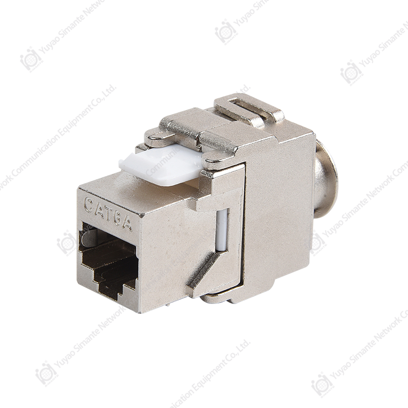
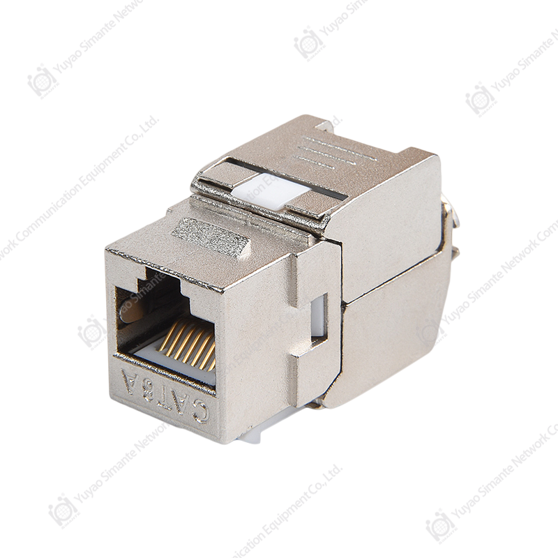
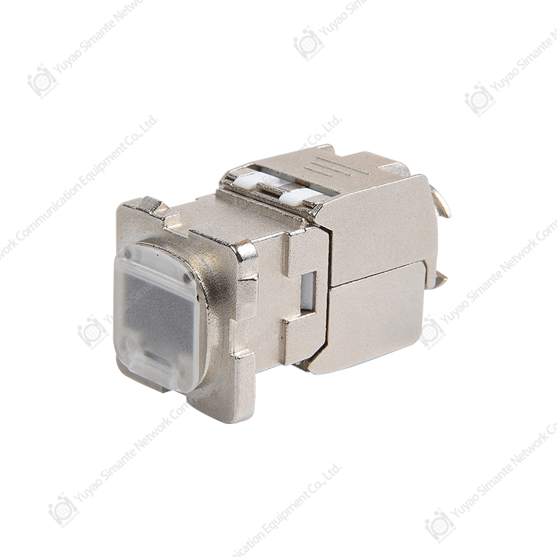
The SMT-1021D8C5E 180 Degree CAT5E Keystone Jack is designed for this essential role. It is a Category 5E modular connection component with a horizontal 180-degree termination orientation, an RJ45 interface, and an IDC termination area compatible with both 110 and Krone-style termination practices. It is intended for structured cabling installations in commercial buildings, offices, residential projects, communication rooms, work areas, smart-home systems, and other low-voltage network environments.
The product is designed around the T568A and T568B wiring sequences and includes a clearly marked universal wiring label on the cable holder. This labeling helps installers identify the correct conductor positions quickly and accurately. Its snap-lock termination cap helps hold conductors in place during termination, reducing the possibility of wire movement or slippage after the conductors have been positioned.
Beyond its basic connection function, the jack combines several design features that support practical field installation. These include an embedded modular structure, a compact body, high-low dislocation contact technology for crosstalk control, phosphor bronze contact materials, gold-plated contact pins, a PC polycarbonate housing, and a termination system suitable for 22–26 AWG twisted-pair cable.
Manufactured by Yuyao Simante Network Communication Equipment Co., Ltd., the product is supported by an established design, production, testing, and customization system. The company develops network cabling products such as keystone jacks, patch panels, wall faceplates, data sockets, and related components. Its manufacturing capabilities include automated and semi-automated injection molding, automatic assembly equipment, multiple regular and customized production lines, engineering support, and export experience across several international markets.
1. Product Overview and Application Position
The SMT-1021D8C5E is a Category 5E keystone jack intended to connect horizontal network cabling with equipment or outlets in the work area. In a typical structured cabling installation, the permanent link runs from a telecommunications room or distribution frame toward a user location. At the work area, the horizontal cable is terminated on a module, and a patch cord or equipment cable connects the RJ45 port to a computer, telephone, wireless access point, camera, automation controller, or other network device.
The jack can also be installed in a modular distribution frame or compatible faceplate. Its embedded design allows the module to be integrated into a larger cabling system without requiring a dedicated, non-standard enclosure. This modularity is important because network installations frequently combine several service types in the same panel, including data, voice, video, fiber, and specialized low-voltage connections.
The 180-degree orientation is particularly practical where the termination area is positioned horizontally behind a faceplate, patch panel, or distribution frame. It can help organize cable routing and reduce unnecessary bends in confined spaces. Installers may also benefit from a more predictable cable-entry direction when several modules are mounted side by side.
The product is designed for Category 5E transmission requirements and a frequency range of 1–100 MHz. Category 5E remains widely used for office networks, building automation, security systems, residential Ethernet, and many general-purpose data installations. It provides a practical balance between performance, availability, and installation cost for applications that do not require higher-category components.
Typical applications
The SMT-1021D8C5E can be used in office structured cabling systems, residential data outlets, commercial buildings, educational facilities, retail spaces, industrial control areas, smart-home installations, communication cabinets, equipment rooms, and work-area connection points.
It is suitable for systems in which the horizontal cable is terminated with an IDC connection and the user-side device is connected through an RJ45 plug. Common connected devices include desktop computers, IP phones, wireless access points, network printers, access-control equipment, building management controllers, surveillance devices, and other Ethernet-compatible equipment.
The jack is intended to mate with connectors and cables from the same standard series. Using components with compatible electrical and mechanical characteristics helps maintain a consistent channel design and reduces the risk of mismatch between the jack, patch cord, plug, and associated hardware.
2. Key Product Advantages
2.1 Dual wiring-sequence support
The product supports both T568A and T568B wiring sequences. These two sequences are widely recognized in structured cabling, and the ability to use either sequence gives installers flexibility when matching an existing project specification.
The wiring sequence should be selected according to the project design and applied consistently throughout the link. The clearly printed wiring information on the cable holder assists the installer in identifying conductor positions during termination. This is especially valuable in large projects where many modules must be terminated in succession and where small wiring errors can lead to testing failures or service calls.
Compared with an unmarked or poorly labeled module, a clearly identified jack can reduce dependence on memory and minimize the chance of transposed pairs. The result is a more repeatable installation process and easier verification by supervisors or quality-control personnel.
2.2 110 and Krone IDC compatibility
The SMT-1021D8C5E uses an IDC termination structure compatible with common 110 and Krone-style termination practices. IDC technology creates an electrical connection by pressing the insulated conductor into a slotted contact. The slot displaces the insulation and establishes contact with the conductor without requiring the installer to strip the wire manually.
This approach offers several practical benefits. It supports fast termination, reduces preparation steps, and helps create consistent connections when the appropriate punch-down tool and installation method are used. Compatibility with familiar termination practices also means that installers do not need to adopt an entirely unfamiliar process when using the module.
The IDC terminal is specified for 22–26 AWG twisted-pair cable. The cable type and conductor size should be checked before installation to confirm that they fall within the intended range. Correct cable seating is important because incomplete insertion, excessive untwisting, or improper tool use can affect both mechanical retention and transmission performance.
2.3 Snap-lock termination cap
A snap-lock termination cap is incorporated to help secure the conductors after they have been placed in the correct IDC positions. During installation, a conductor may shift if it is not adequately supported or if the cable is moved before the termination process is completed. The cap helps keep the wire arrangement stable and reduces the possibility of slippage.
This feature is useful in high-volume installations, where the time saved on correcting displaced conductors can be significant. It also contributes to a cleaner and more controlled termination appearance. A stable cable arrangement makes it easier for technicians to inspect the completed module and confirm that the pairs follow the selected wiring sequence.
2.4 High-low dislocation contact technology
The contact pins use a high-low dislocation arrangement intended to reduce near-end crosstalk. Crosstalk occurs when electrical energy from one pair or circuit couples into another nearby pair. In twisted-pair cabling, proper pair geometry, contact design, conductor separation, and termination quality all contribute to maintaining signal integrity.
The high-low dislocation structure separates contact positions in a way that helps control unwanted coupling near the connector interface. This is a meaningful advantage over basic connector designs that may place contact structures too close together or provide less attention to pair-to-pair interaction.
The stated product specification lists near-end crosstalk attenuation as at least 6 dB under the applicable test conditions. Actual installed performance also depends on cable construction, plug quality, patch-cord design, installation workmanship, grounding conditions where relevant, and the performance of the complete channel. The jack should therefore be evaluated as part of the full structured cabling system rather than as an isolated component.
2.5 Compact modular construction
The compact form factor allows the jack to be used in modular faceplates and distribution frames. A compact module can simplify the installation of multiple ports in a limited space and can support a neat cable-management arrangement behind the panel.
The embedded design also allows the module to be integrated into an overhead distribution frame or modular distribution frame. This flexibility is valuable for projects that require a consistent module format across different mounting locations. Standardized modules can simplify stocking, installation training, maintenance, and replacement procedures.
2.6 Durable contact materials
The contact pins are made from phosphor bronze with a gold-plated surface. Phosphor bronze is commonly used in electrical contacts because it combines spring characteristics, mechanical strength, and resistance to deformation. The gold-plated contact surface is intended to support stable electrical contact and help protect the contact area against oxidation under appropriate operating conditions.
The IDC card-wire terminals use phosphor bronze with nickel plating. Nickel plating provides a durable surface for the termination contact and supports the mechanical demands associated with punch-down installation. The specified gold-plating range for the contact pins is 6–50U, according to the supplied technical information. The exact plating level may be confirmed according to the customer’s order specification and quality documentation.
2.7 Robust plastic housing
The non-metallic housing is made from PC polycarbonate. Polycarbonate is widely used for electrical and communication components because it offers a useful combination of strength, dimensional stability, insulation properties, and resistance to impact during normal handling.
A stable housing is important because the jack must hold the contact system in a controlled position while receiving RJ45 plugs and supporting an IDC termination. The housing also needs to retain its shape during assembly, installation, and routine maintenance. The use of PC material helps provide a practical foundation for these requirements.
2.8 RoHS-conscious material selection
The product is designed to meet RoHS requirements. Compliance with restrictions on certain hazardous substances is important for international supply chains, commercial construction projects, and customers that maintain environmental or procurement standards.
RoHS compliance should be supported by the applicable material declarations, production controls, and customer documentation required for the destination market. For large projects, buyers can request confirmation of the current compliance status and relevant test or declaration records before final approval.
3. Technical Performance and Specifications
The following table summarizes the principal technical information provided for the SMT-1021D8C5E.
| Item | Specification |
|---|---|
| Product type | 180-degree Category 5E keystone jack |
| Connector interface | RJ45 jack with jumper connection |
| IDC termination | Horizontal wiring, compatible with 110 and Krone-style termination practices |
| Wiring sequences | T568A and T568B |
| Frequency range | 1–100 MHz |
| Working voltage | 125 V |
| Withstand voltage | DC 1000 V or AC 750 V for 1 minute, without breakdown or arcing |
| Near-end crosstalk attenuation | At least 6 dB |
| Initial insulation resistance | At least 100 MΩ |
| Insulation resistance after damp-heat testing | At least 100 MΩ |
| Insertion force | Not more than 20 N |
| Pull-out force | Not less than 20 N |
| Connector connection-device test | 50 N for 60 ± 5 seconds |
| IDC cable range | 22–26 AWG twisted-pair cable |
| RJ45 insertion and withdrawal durability | 750 cycles |
| Wire termination durability | 250 terminations |
| Contact material | Phosphor bronze with gold plating |
| IDC terminal material | Phosphor bronze with nickel plating |
| Housing material | PC polycarbonate |
| PCB material | FR4 |
| Operating temperature | -25°C to +70°C |
| Environmental humidity specification | Up to 85%, according to the supplied technical information |
| Applicable general specification | YD/T 926.1-2009 |
| Applicable sub-standard | YD/T 926.3-2009 |
The electrical specifications indicate that the module is designed for standard low-voltage communication use within its specified operating range. A withstand-voltage rating of DC 1000 V or AC 750 V for one minute without breakdown or arcing provides an important indication of dielectric strength under the stated test conditions.
The insulation resistance specification of at least 100 MΩ, both initially and after the constant damp-heat test, supports the objective of maintaining separation between conductive elements. Such characteristics are important in environments where moisture, temperature variation, or long operating periods may place greater demands on the insulating system.
The mechanical specifications address both installation and service life. The stated insertion force of no more than 20 N helps support convenient patch-cord connection, while a pull-out force of at least 20 N helps maintain a secure connection. The specified 750 plug-and-socket cycles and 250 wire terminations are relevant to installations that may undergo repeated maintenance, reconfiguration, or equipment replacement.
These values should be interpreted together with the applicable test methods and production-batch records. Customers with project-specific requirements may request sample testing, inspection reports, or confirmation of the exact test conditions before approving the product for a large deployment.
4. Installation Benefits in Structured Cabling Projects
Installation labor is one of the largest cost elements in many structured cabling projects. The product’s value therefore extends beyond its material price. A module that is easy to identify, terminate, inspect, and replace can improve the total cost of ownership even when its unit price is comparable to other products.
4.1 Faster conductor identification
The universal wiring sequence label is clearly marked on the cable holder. During installation, the technician can place the conductors against the selected T568A or T568B sequence and verify the position before punching down. This supports a repeatable workflow and can reduce the time spent consulting separate documentation.
4.2 Reduced risk of wire movement
The snap-lock termination cap supports conductor retention before and during IDC termination. This is especially helpful when the module is installed in a location where the cable must be routed, dressed, or repositioned immediately after termination.
4.3 Convenient use in dense panels
The compact 180-degree configuration helps organize terminations in distribution frames and modular panels. When numerous ports are installed close together, a predictable orientation can simplify cable routing and make the rear of the panel easier to inspect.
4.4 Easier maintenance and replacement
Because the product follows a modular keystone format, a damaged or obsolete module can generally be replaced without rebuilding the entire faceplate or distribution assembly. The modular concept is particularly useful in offices and buildings where moves, adds, and changes are common.
4.5 Consistent training requirements
Installers who already understand RJ45 and IDC termination methods can apply familiar practices to this product. This can simplify workforce training, especially for contractors who are deploying large numbers of modules across multiple floors or buildings.
5. Comparison with Basic or Less Specialized Keystone Jacks
Product selection should be based on the complete application rather than on appearance alone. Many basic keystone jacks may provide an RJ45 interface, but differences in labeling, contact layout, material selection, termination retention, durability, and manufacturing control can influence project results.
Compared with an unmarked module, the SMT-1021D8C5E provides clearer conductor guidance through its universal wiring label. Compared with a module that lacks a dedicated retention feature, its snap-lock cap offers additional support for maintaining conductor position. Compared with a basic contact arrangement, the high-low dislocation structure is intended to improve control of near-end crosstalk.
The product also combines a compact embedded design with compatibility for modular distribution frames. This may be preferable to a proprietary format that limits replacement options or requires a special mounting system. Its use of phosphor bronze contact components, plated surfaces, polycarbonate housing material, and FR4 board material further supports a controlled construction approach.
In addition, the product is supported by a manufacturer with dedicated engineering, tooling, molding, assembly, and testing resources. This is an important distinction for buyers who need more than a one-time shipment. Stable production capacity, documented inspection procedures, customization support, and ongoing technical communication can be valuable when a project involves multiple batches or regional deployments.
It is important not to assume that any individual connector will automatically outperform every competing product in every installation. Performance depends on the entire cabling channel and on compliance with the relevant project requirements. However, the combination of installation-oriented features, specified materials, mechanical durability, and production support gives this model a strong position among practical Category 5E modular connection products.
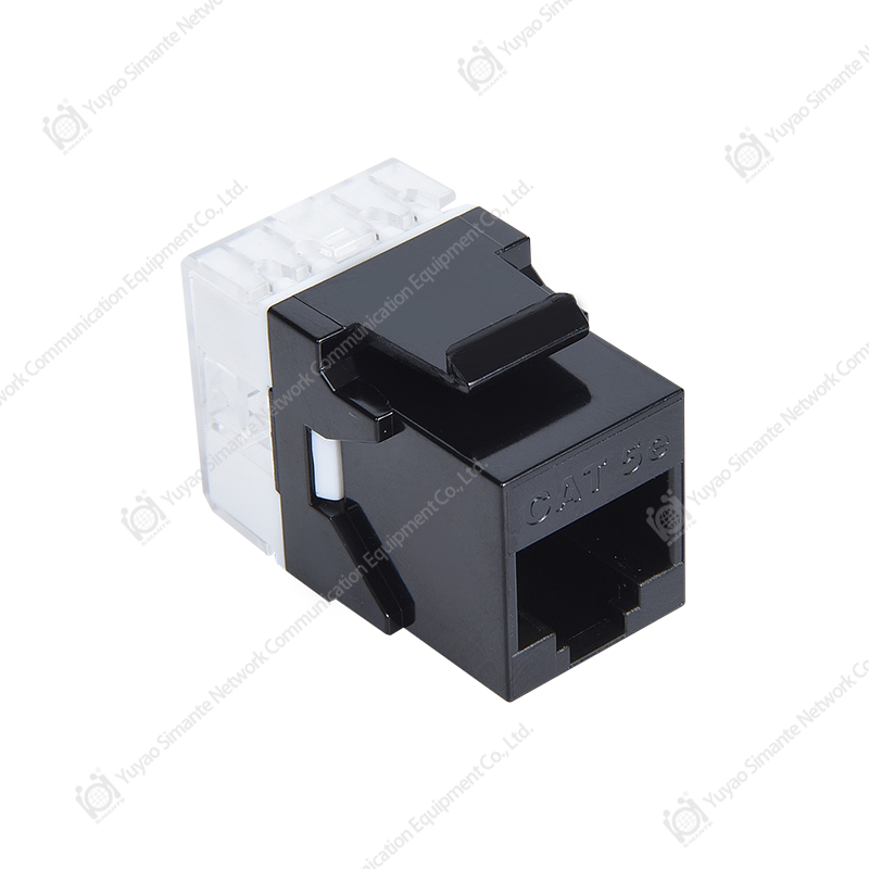
SMT-1021D8C5E 180 Degree CAT5E Keystone Jack 110 & Krone IDC
6. Manufacturing Strengths and Quality-Control Approach
Yuyao Simante Network Communication Equipment Co., Ltd. integrates design, development, sales, and service. This integrated structure allows product decisions to be coordinated across engineering, tooling, production, inspection, and customer support rather than treating each function as an isolated activity.
6.1 Product development and engineering support
The company reports a mature research and development system supported by more than ten engineers and more than thirty full-time technical personnel. This engineering base can contribute to product refinement, mold development, production troubleshooting, customization, and technical documentation.
For structured cabling products, engineering control is particularly important because small changes in contact geometry, plastic dimensions, spring pressure, labeling, or assembly alignment can affect the final result. An experienced technical team can review these details during design and help translate customer requirements into a manufacturable product.
6.2 Injection-molding capability
The factory operates automatic and semi-automatic injection-molding equipment, including ten fully automatic injection-molding machines and twenty semi-automatic machines according to the supplied company information. Injection molding is central to the production of keystone jack housings, caps, clips, and other plastic parts.
Consistent molding requires control of resin selection, drying conditions where applicable, mold temperature, injection pressure, cooling time, cycle time, dimensional tolerances, and visual quality. Stable molding parameters help ensure that the housing fits correctly with the contact assembly and that the finished module can be installed in compatible panels.
Automated molding can help improve repeatability and production efficiency. Semi-automatic equipment can provide flexibility for product variations, smaller batches, or customized parts. The combination of both equipment types can support both regular-volume production and special project requirements.
6.3 Automatic assembly resources
The company reports eight automatic installation or assembly machines. Automatic assembly can support consistent placement of contacts, terminals, clips, caps, and other parts. It can also reduce variation caused by manual operations when the product design is suitable for automation.
Automation does not eliminate the need for skilled personnel. Instead, it allows technicians and quality staff to focus on process setup, parameter control, inspection, maintenance, and improvement. A well-managed automated process can help stabilize output while preserving the flexibility required for multiple product models.
6.4 Multiple production lines
The factory has ten regular and customized production lines. This production structure can support a broad portfolio of network cabling products and can help separate standard orders from customized projects when scheduling requires it.
For buyers, multiple lines may provide practical advantages such as improved order coordination, greater capacity for repeat orders, and reduced dependence on a single production cell. Customers can discuss model-specific capacity, lead times, packaging requirements, and quality-control arrangements during the quotation and order-confirmation stages.
6.5 Production scale and supply continuity
The company reports a stable annual output of more than nine million units across its product range. A substantial production base can be important for distributors, contractors, and original-equipment customers that need consistent supply over an extended project period.
Supply continuity is not only a question of production volume. It also depends on component sourcing, mold maintenance, process documentation, operator training, warehouse management, and final inspection. An integrated manufacturing organization can coordinate these areas and help preserve model consistency between batches.
6.6 Quality testing and inspection
The company emphasizes performance testing as part of its manufacturing approach. For a keystone jack, relevant inspections may include visual appearance, dimensional accuracy, contact alignment, insertion and withdrawal force, IDC retention, insulation resistance, dielectric withstand, crosstalk-related testing, plating verification, and durability testing.
Testing should be performed according to the applicable product specification and agreed customer requirements. Production inspection can identify defects before shipment, while sample-based qualification testing can confirm that the design continues to meet its intended performance targets.
Customers requiring formal project documentation may request inspection records, sample approval procedures, material declarations, packaging confirmation, and other quality documents. These arrangements are especially useful for construction projects, government procurement, telecommunications installations, and private-label programs.
7. Material and Environmental Considerations
Material selection affects electrical performance, mechanical reliability, appearance, environmental compliance, and service life. The SMT-1021D8C5E uses phosphor bronze for the primary contact components, with gold plating on the contact pins and nickel plating on the IDC terminals.
Gold plating is used on the contact interface to support stable mating performance. The plating thickness can influence durability and corrosion resistance, so buyers should confirm the required value for the intended application. The supplied specification gives a range of 6–50U, and the final value may be selected according to the customer’s order or product configuration.
The PC polycarbonate body provides electrical insulation and mechanical support. The FR4 material is used for the PCB portion of the product. These materials are commonly associated with communication and electronic assemblies where dimensional stability and insulation are important.
The stated operating temperature range is -25°C to +70°C. This range covers many indoor commercial and residential applications, although the actual installation environment should be evaluated before deployment. Direct sunlight, condensation, chemical exposure, severe dust, outdoor moisture, and high heat may require additional enclosure or environmental protection.
The supplied technical information also identifies humidity conditions up to 85 percent and references constant damp-heat testing. Because humidity specifications can depend on temperature, duration, and test method, project engineers should verify the exact environmental profile and applicable test conditions when the product will be installed in a demanding location.
Salt-spray test conditions
The product information includes salt-spray test guidance. The salt solution is specified at a pH between 6.5 and 7.2 before atomization, with a sodium chloride concentration of 5 ± 0.1 percent by mass. The recommended continuous atomization duration is 48 hours.
Salt-spray testing is generally used to evaluate the resistance of metallic surfaces under an accelerated corrosive environment. It does not reproduce every real-world installation condition, but it can provide useful comparative information about plating and exposed metal surfaces. During testing, oil, dust, and other impurities should be controlled, and the temperature and humidity of the test air should not interfere with the specified conditions.
In normal service, the module should be installed in a suitable enclosure or indoor structured cabling environment unless the complete assembly has been specifically designed for outdoor or corrosive conditions.
8. Recommended Installation Practice
Before installation, confirm the cable category, conductor gauge, wiring sequence, module orientation, panel compatibility, and required labeling. Verify that the cable is within the specified 22–26 AWG range and that the conductor arrangement matches the selected T568A or T568B sequence.
Route the cable carefully to avoid excessive pulling force, sharp bends, crushing, or unnecessary untwisting. Twisted-pair geometry is part of the cable’s transmission design, and excessive disturbance near the termination area can affect performance. Keep each pair twisted as close as practical to the IDC termination point while following the module’s termination instructions.
Place each conductor into the correct IDC slot according to the chosen wiring sequence. Use the marked guide on the cable holder to confirm the pair order. Engage the snap-lock termination cap as intended, then apply the appropriate punch-down tool with controlled pressure. Remove any excess conductor material cleanly and inspect the termination for proper seating.
After termination, inspect the module for displaced wires, damaged insulation, cracked plastic, incomplete seating, or contamination on the contact area. Install the module into the compatible faceplate, patch panel, or distribution frame. Confirm that the retaining features engage correctly and that the cable is supported without placing stress on the termination.
Testing should include wire-map verification and, where required by the project, continuity, resistance, insertion-loss, return-loss, and crosstalk measurements. A complete link test is more informative than testing the jack alone because it evaluates the interaction of the cable, module, plug, patch cord, and other channel components.
9. Packaging, Storage, and Logistics
The product is placed in a dedicated blister bag and then packed in a cardboard box. Product accessories are included in the packaging, and a label identifying the model and quantity is applied to the upper-left area of the carton front according to the supplied packaging description.
The regular packing quantity is 50 pieces per box, with 10 boxes per carton, for a total of 500 pieces per carton. This arrangement supports organized warehouse handling and makes it easier for distributors or contractors to plan stock quantities.
Packaged products should be stored in a warehouse with an ambient temperature of approximately -5°C to +30°C and relative humidity not exceeding 70 percent. The storage area should be free from acid, alkali, and other corrosive gases. The stated storage period is three years under the recommended conditions.
During transportation and storage, cartons should be protected from impact, water, excessive heat, and deformation. Stock should be rotated according to purchase date, and cartons should remain sealed until the modules are ready for installation. Customers requiring private-label or customer-specified packaging can discuss labeling, carton markings, inner packing, and quantity arrangements with the manufacturer.
10. OEM, ODM, and Customization Potential
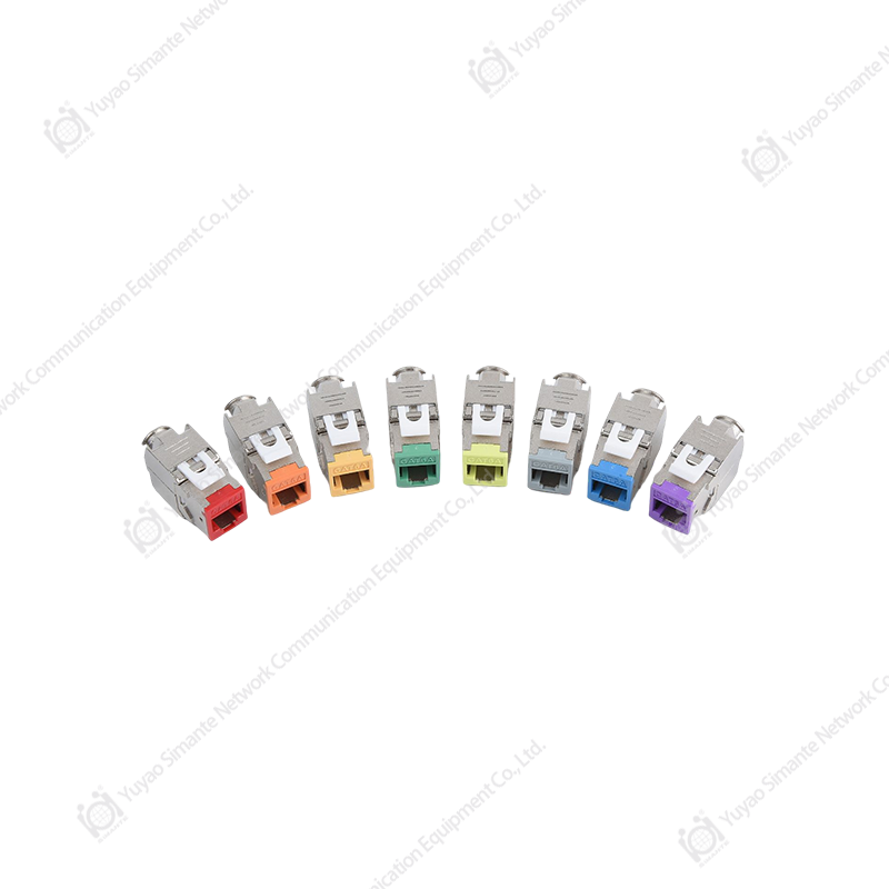
Structured cabling suppliers often require more than a standard catalog product. They may need a specific color, logo, label, packaging format, plating level, housing design, mounting clip, wiring guide, or carton quantity. The manufacturer’s regular and customized production lines provide a foundation for discussing such requirements.
OEM projects may involve producing the module under a customer’s brand or packaging identity. ODM projects may involve adapting an existing structure or developing a product around the customer’s technical requirements. Before proceeding, both parties should confirm drawings, material specifications, tolerances, testing requirements, packaging artwork, order quantities, tooling responsibility, and approval samples.
Customization should preserve the electrical and mechanical properties required by the application. For example, changing a housing material, contact geometry, plating thickness, or termination structure can affect performance and should be reviewed by engineering personnel before mass production.
The company’s experience with network communication products gives it a relevant base for supporting distributors, installers, system integrators, and project contractors. Its export activity in Europe, Australia, Africa, the Middle East, and Southeast Asia also indicates experience in serving customers with different documentation, packaging, and supply-chain expectations.
11. Selecting the Product for a Project
Project buyers should begin by identifying the required cabling category and the expected network application. The SMT-1021D8C5E is designed for Category 5E systems operating over the stated 1–100 MHz frequency range. If a project requires a higher category or a specific performance class, the entire channel should be designed using matching components that satisfy that requirement.
Next, confirm the mounting format. The module is intended for compatible modular faceplates, frames, and distribution systems. Check the panel opening, retention method, rear clearance, cable-entry direction, and available space before placing a large order.
Confirm the conductor size and termination method. The module is specified for 22–26 AWG twisted-pair cable and uses an IDC termination structure. If the project uses a different conductor size, stranded patch cable, shielded cable, or a specialized connector, technical confirmation should be obtained before selection.
Environmental conditions should also be reviewed. Indoor office and residential applications are generally straightforward, but industrial rooms, unconditioned spaces, humid areas, chemical-processing locations, and outdoor cabinets may require additional protection or a different product design.
Finally, buyers should define inspection and documentation requirements. These may include sample approval, packaging confirmation, RoHS documentation, plating verification, mechanical test records, electrical test records, labeling, and traceability information. Early agreement helps reduce confusion during production and delivery.
12. Frequently Asked Questions
Q1: What type of product is the SMT-1021D8C5E?
It is a 180-degree Category 5E keystone jack with an RJ45 interface and an IDC termination area. It is designed to connect horizontal twisted-pair cabling with equipment or work-area outlets.
Q2: Does it support both T568A and T568B?
Yes. The jack is designed to support both T568A and T568B wiring sequences. The selected sequence should be applied consistently throughout the relevant cabling link.
Q3: What does 110 and Krone IDC mean?
It refers to compatibility with common insulation-displacement termination practices associated with 110 and Krone-style terminal arrangements. The conductor is pressed into the IDC slot, allowing the contact to displace the insulation and establish an electrical connection.
Q4: What cable sizes are supported?
The IDC terminal is specified for 22–26 AWG twisted-pair cable. The cable construction and conductor type should also be confirmed before installation.
Q5: What is the purpose of the snap-lock termination cap?
The cap helps hold the conductors in their correct positions during and after termination. It can reduce wire movement and make the completed termination easier to inspect.
Q6: How does the high-low contact arrangement help?
The high-low dislocation contact structure is intended to reduce near-end crosstalk by controlling the physical relationship between contact positions. The final transmission performance still depends on the complete cabling channel and installation quality.
Q7: What materials are used for the contacts and housing?
The contact pins use gold-plated phosphor bronze, while the IDC terminals use nickel-plated phosphor bronze. The housing is made from PC polycarbonate, and the PCB material is FR4.
Q8: How durable is the jack?
The supplied specifications list 750 RJ45 plug insertion and withdrawal cycles and 250 wire terminations. The product also includes mechanical requirements for insertion force, pull-out force, and connector connection-device loading.
Q9: Can the module be installed in a distribution frame?
Yes. Its embedded modular design allows it to be installed in a compatible overhead or modular distribution frame, as well as suitable faceplates and other modular mounting systems.
Q10: Is the product suitable for outdoor installation?
The product is primarily intended for structured cabling environments that remain within its specified temperature, humidity, and material conditions. Outdoor or corrosive installations require an appropriate enclosure and should be reviewed with the manufacturer before use.
Q11: Is the product RoHS compliant?
The supplied product information states that the design meets RoHS requirements. Buyers requiring formal documentation should request the current declaration or relevant compliance records for the purchased configuration.
Q12: What is the regular packing quantity?
The regular packing quantity is 50 pieces per box and 10 boxes per carton, for 500 pieces per carton.
Q13: Can custom packaging be arranged?
Yes. The product information indicates that customer-specified packaging can be supported. Packaging artwork, labels, carton quantities, and accessory arrangements should be confirmed before production.
Q14: Can the manufacturer support OEM or ODM projects?
Yes. The company undertakes OEM and ODM projects and operates regular and customized production lines. Customized projects should be supported by approved drawings, samples, specifications, and testing requirements.
Q15: What information should be provided when requesting a quotation?
Useful information includes required quantity, cable category, wiring sequence, housing color, contact-plating requirement, mounting format, packaging design, labeling, destination market, inspection requirements, and target delivery schedule.
13. Why This Product Is a Practical Choice
The SMT-1021D8C5E combines features that address the most common practical concerns in Category 5E termination: correct conductor placement, secure IDC termination, controlled contact geometry, modular installation, contact durability, and repeatable production.
Its support for T568A and T568B provides wiring flexibility. The clearly marked cable holder assists installation accuracy. The snap-lock cap helps maintain conductor position. The high-low contact design is intended to reduce near-end crosstalk. The 180-degree layout supports organized rear-side routing. Gold-plated phosphor bronze contacts and a polycarbonate housing provide a material platform suited to repeated use in structured cabling systems.
These product features are supported by manufacturing capabilities that include engineering development, automated molding, semi-automatic production, automatic assembly, quality testing, customized production, and international supply experience. For customers seeking a stable source of network cabling components, the manufacturer’s ability to coordinate design and production can be as important as the specifications of the individual jack.
For best results, the module should be installed with compatible Category 5E cable, plugs, patch cords, panels, and accessories. The selected wiring sequence should be applied consistently, and the completed channel should be tested according to the project standard. When these practices are followed, the SMT-1021D8C5E can provide an efficient and dependable connection point for a wide range of copper structured cabling applications.

14. Conclusion
The SMT-1021D8C5E 180-degree CAT5E keystone jack is designed for installers and system suppliers that need a practical, modular, and repeatable copper-cabling connection component. Its 110 and Krone IDC compatibility, T568A and T568B support, clearly marked wiring guide, snap-lock termination cap, high-low contact arrangement, compact form, and durable contact materials address both installation efficiency and long-term usability.
The product’s electrical, mechanical, durability, material, and environmental specifications provide a clear basis for project evaluation. Its modular format supports faceplates, distribution frames, and other structured cabling assemblies, while its 180-degree orientation can help improve cable organization in confined spaces.
Equally important, the manufacturing organization behind the product offers engineering support, injection-molding resources, automatic assembly capability, customized production lines, performance testing, OEM and ODM support, and international supply experience. This combination makes the product suitable not only for individual installations but also for larger distribution programs, building projects, and private-label network cabling solutions.
When selected as part of a properly matched and tested Category 5E channel, the SMT-1021D8C5E provides a balanced solution for commercial, residential, communication, automation, and smart-building applications.
References
1. YD/T 926.1-2009, General Specification for Communication Cables and Connection Hardware in Structured Cabling Systems.
2. YD/T 926.3-2009, Sub-Standard Requirements for Communication Cables and Connection Hardware in Structured Cabling Systems.
3. TIA-568 Structured Cabling Standards, Balanced Twisted-Pair Cabling and Component Installation Practices.
4. IEC 60603-7 Series, Connectors for Electronic Equipment and Modular Interface Requirements.
5. IEC 60512 Series, Connectors for Electronic Equipment: Tests and Measurements.
6. RoHS Restriction Requirements for Hazardous Substances in Electrical and Electronic Equipment.
7. Product technical information for the SMT-1021D8C5E 180-Degree CAT5E Keystone Jack with 110 and Krone IDC termination.
8. Manufacturer-provided information concerning production capacity, engineering resources, material selection, packaging, and customization services.