Español
 عربى
 русский
Content
- 1 Product Overview
- 2 Why an Inline Coupler Is Important in Structured Cabling
- 3 Category 6A Transmission Capability
- 4 360-Degree Shielding and Electromagnetic Compatibility
- 5 Mechanical Design for Modular Installation
- 6 Materials and Surface Treatment
- 7 Electrical and Mechanical Specifications
- 8 Advantages Compared with Basic Unshielded Adapters
- 9 Advantages Compared with Field-Terminated Cable Extensions
- 10 Manufacturing Strengths and Process Control
- 11 Standards and Compliance
- 12 Applications in Commercial and Industrial Networks
- 13 Installation Recommendations
- 14 Packaging, Storage, and Logistics
- 15 Customization, OEM, and ODM Support
- 16 Purchasing Considerations for Distributors and System Integrators
- 17 Frequently Asked Questions
- 17.1 What is the SMT-1024T8C6A-FTP used for?
- 17.2 Does the coupler support both T568A and T568B?
- 17.3 Is the product shielded?
- 17.4 Can it be installed in a patch panel?
- 17.5 What is the supported frequency range?
- 17.6 What materials are used in the product?
- 17.7 How many insertion cycles can the coupler withstand?
- 17.8 Can it be used outdoors?
- 17.9 Can the coupler be used with Power over Ethernet?
- 17.10 What standards are associated with the product?
- 17.11 How should the product be stored?
- 17.12 What is the standard packing quantity?
- 17.13 Does the manufacturer support custom packaging?
- 18 Conclusion
- 19 References
- 20 Product: SMT-1024T8C6A-FTP Shielded CAT6A Inline Coupler

Modern communication networks depend on small connection components as much as they depend on large-scale infrastructure. A patch panel, cable, switch, or server may receive most of the attention, but the quality of the connector between two network cables can directly influence installation efficiency, signal continuity, electromagnetic compatibility, and long-term serviceability. The SMT-1024T8C6A-FTP Shielded CAT6A Inline Coupler is designed to provide a practical, compact, and dependable connection point for Category 6A copper networks.
This inline coupler is intended for direct RJ45-to-RJ45 connection and extension of compatible twisted-pair Ethernet cables. It supports T568A and T568B wiring sequences, uses a straight-through one-to-one contact arrangement, and is suitable for communication connections between equipment and work areas. Its embedded keystone-style form allows it to be used with compatible panels and patch panels, while its zinc alloy shielding enclosure helps reduce the impact of electromagnetic interference in demanding installation environments.
For structured cabling contractors, system integrators, network equipment distributors, and original equipment manufacturers, the product combines the functional advantages of a compact keystone module with the convenience of an inline RJ45 coupler. It is designed for stable production, repeatable assembly, easy installation, and broad application across commercial buildings, data communication systems, automation projects, smart homes, and other copper network environments.
Product Overview
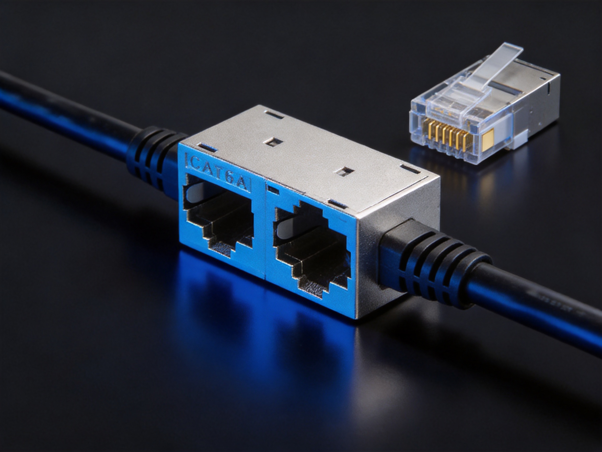
The SMT-1024T8C6A-FTP is a shielded CAT6A inline coupler classified as a CAT6A keystone jack. Both ends of the module are equipped with RJ45 sockets, allowing two terminated network cables to be joined without the need for field splicing or additional termination work. The coupler creates a straight-through connection from one RJ45 port to the other and is designed for use with copper twisted-pair network cables and copper patch cords.
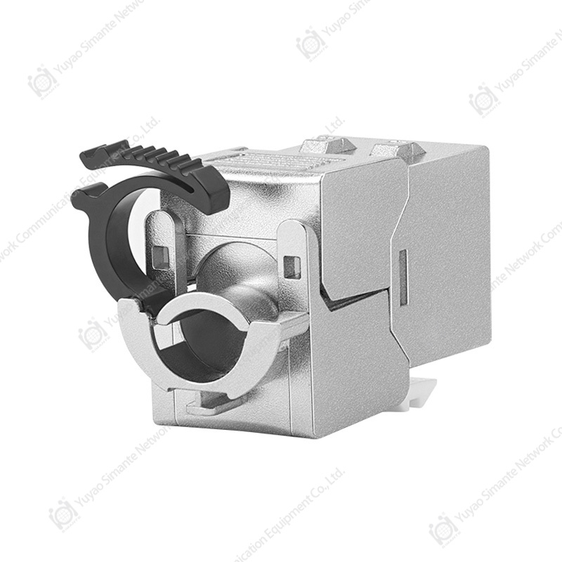
The compact construction is suitable for installation in compatible wall plates, surface boxes, patch panels, and other modular structured cabling hardware. The module can be fixed through its card position, helping installers produce a neat and organized connection layout. This embedded design also allows the coupler to be incorporated into a larger structured cabling system without occupying unnecessary space.
The product is engineered for Category 6A transmission requirements and supports a frequency range of 1 to 500 MHz. This makes it suitable for high-bandwidth copper network installations where performance, shielding, and mechanical reliability are important. The all-metal zinc alloy die-cast housing provides a durable external structure, while the 360-degree shielding design is intended to help prevent or reduce electromagnetic interference around the connection point.
In addition to its electrical and mechanical functions, the coupler is designed with environmental compliance and production consistency in mind. Its materials include phosphor bronze contacts with gold plating, a Zamak 5 nickel-plated housing, PC polycarbonate insulation components, and an FR4 printed circuit board. The product is also specified to meet RoHS requirements.

SMT-1024T8C6A-FTP Shielded CAT6A Inline Coupler
Why an Inline Coupler Is Important in Structured Cabling
Structured cabling installations frequently require cable extensions, equipment relocations, temporary connections, or transitions between different sections of a network. In many cases, the original cable length is not sufficient, or a cable route must be modified after the initial installation. An inline coupler provides a simple method for joining two cables while preserving a modular connection architecture.
Without a suitable coupler, installers may need to cut and reterminate cables, install an additional wall outlet, or use improvised connection methods. These alternatives can increase installation time and create more opportunities for wiring errors. A dedicated CAT6A inline coupler simplifies the process by providing two standardized RJ45 interfaces in a single housing.
The coupler also supports easier maintenance. If a cable is damaged, the affected cable can be disconnected and replaced without disturbing the permanent cabling on the other side. This modular service approach can reduce downtime and make troubleshooting more efficient, especially in offices, equipment rooms, security systems, educational facilities, and industrial communication networks.
For installers, another advantage is consistency. A properly manufactured inline coupler provides a repeatable contact arrangement and controlled mechanical interface. Compared with field-created connections, a factory-assembled module can offer more predictable insertion force, retention, contact alignment, shielding continuity, and visual quality.
Category 6A Transmission Capability
Category 6A cabling is commonly selected for high-speed Ethernet applications and structured cabling systems that require greater bandwidth and improved resistance to interference. The SMT-1024T8C6A-FTP coupler is designed around the transmission requirements associated with CAT6A systems and provides a connection interface suitable for compatible shielded copper cabling.
The specified frequency range is 1 to 500 MHz. A higher operating frequency range places greater demands on contact geometry, pair balance, signal path continuity, insulation quality, and internal layout. At these frequencies, small changes in the physical arrangement of conductive elements can influence insertion performance and crosstalk behavior. The coupler therefore uses an organized internal contact structure and a compact design intended to maintain a controlled signal path.
The product supports both T568A and T568B wiring sequences. This is important because structured cabling projects may use either recognized termination scheme depending on regional practice, installation specifications, or the existing wiring system. Supporting both sequences gives distributors and installers greater flexibility while helping the module integrate with a broad range of standard RJ45 cable assemblies.
The connection method is a one-to-one straight-through configuration. Pin 1 on one side is connected to pin 1 on the other side, and the remaining contacts follow the corresponding straight-through arrangement. This makes the coupler suitable for joining compatible network cables without introducing an intentional crossover function.
Contact Geometry and Crosstalk Control
Near-end crosstalk is one of the important considerations in high-frequency copper cabling. Crosstalk occurs when energy from one pair or circuit path couples into another nearby path. If not controlled, it can reduce signal quality and limit network performance. The product uses a high-and-low staggered contact pin arrangement intended to improve separation between contact paths and reduce near-end crosstalk.
The provided technical specification identifies a near-end crosstalk attenuation value of at least 3 dB. Actual system performance depends on the entire channel, including the cable, plugs, patch panels, installation geometry, grounding, and environmental conditions. Nevertheless, the internal contact arrangement provides a deliberate design approach rather than relying only on basic pin alignment.
This design is particularly useful in dense patching environments where multiple modules and cables are installed close together. A controlled internal structure can support better consistency between production batches and help installers build compact network layouts without unnecessarily increasing the footprint of the connection hardware.
360-Degree Shielding and Electromagnetic Compatibility
One of the key features of the SMT-1024T8C6A-FTP is its 360-degree shielding shell. The shield surrounds the connection area to provide all-round conductive coverage rather than protecting only one surface. This construction is intended to reduce exposure to electromagnetic interference and help maintain a more stable electrical environment around the signal contacts.
Electromagnetic interference can originate from power cables, motors, transformers, lighting systems, industrial equipment, wireless transmitters, and other electronic devices. In commercial and industrial installations, network cables may run through crowded pathways where copper communication lines are located near sources of electrical noise. Shielded components can help improve the resistance of the overall cabling channel when the cable, connector, patch panel, and grounding system are designed as a compatible shielded system.
The metal shell is made from Zamak 5 zinc alloy and receives a nickel-plated surface treatment. Zinc alloy die casting provides a strong and accurately formed housing while supporting high-volume manufacturing. The nickel-plated finish contributes to surface protection, appearance, and conductivity at the contact interfaces used for shielding continuity.
The grounding design is intended to be reliable and convenient during installation. A well-designed shield must do more than surround the signal contacts; it must also provide a practical path for connection to the system grounding arrangement. The coupler’s metal housing and grounding structure are designed to support this objective when used with compatible shielded cabling and properly grounded system hardware.
It is important to understand that a shielded coupler cannot independently eliminate every source of electromagnetic interference. The final result depends on the complete network channel. Installers should use compatible shielded cables, shielded plugs, grounded patch panels, and appropriate installation practices. When these elements are correctly combined, the coupler can contribute to a more robust shielded structured cabling system.
Mechanical Design for Modular Installation
The embedded form factor is one of the practical advantages of this product. Rather than functioning only as a loose adapter, the coupler can be integrated into compatible modular panels and patch panels. The card-position fixing method helps hold the module in place and creates a cleaner appearance than an unsecured external adapter.
Modular installation is useful in office outlets, communication cabinets, equipment racks, data centers, control rooms, and building distribution systems. It allows the same basic module format to be used in different installation accessories, simplifying product selection and inventory management. A distributor can supply the coupler as part of a broader keystone-based product family, while an installer can use it in locations that require a direct cable-to-cable connection.
The zinc alloy housing also provides a solid mechanical enclosure around the RJ45 sockets. A metal housing can offer greater rigidity than a lightweight plastic-only adapter, particularly when cables are connected and disconnected repeatedly. The reinforced enclosure helps protect the internal contact system against ordinary handling forces during installation and maintenance.
The specified insertion force is not more than 20 N, while the pull-out force is not less than 20 N. These values reflect the need for a practical balance: the plug should insert smoothly without excessive effort, but it should also remain securely connected during normal cable handling. The product specification further identifies a connector connection-device test of 50 N for 60 ± 5 seconds, representing a mechanical resistance evaluation under applied force.
Materials and Surface Treatment
The selection of materials affects electrical conductivity, mechanical durability, corrosion resistance, dimensional stability, and manufacturing reliability. The product uses several materials selected for their specific roles within the coupler.
Phosphor Bronze Gold-Plated Contacts
The contact pins are made from phosphor bronze and plated with gold. Phosphor bronze provides a combination of electrical conductivity, spring properties, and mechanical resilience. These properties are valuable for RJ45 contacts that must maintain pressure against the mating plug over repeated insertion and removal cycles.
The gold-plated surface helps protect the contact area from oxidation and supports stable electrical contact. The stated gold-plating thickness range is 6 to 50U. The exact thickness may depend on the relevant product configuration or production requirement. For procurement projects, buyers can confirm the applicable plating specification, inspection standard, and acceptance criteria with the manufacturer before placing an order.
Zamak 5 Nickel-Plated Housing
Zamak 5 zinc alloy is used for the main metal housing. Zinc alloy die casting supports the production of complex shapes with repeatable dimensions and integrated mechanical features. It is well suited to compact connector shells that require structural strength, shielding coverage, and accurate fitting with modular panels.
The nickel-plated surface provides a consistent metallic finish and contributes to corrosion resistance and shielding contact performance. The housing is designed to provide all-round shielding around the connector assembly, making it particularly appropriate for FTP and other shielded structured cabling applications.
PC Polycarbonate Insulation
PC polycarbonate is used for non-metallic components. Polycarbonate is recognized for impact resistance, dimensional stability, and suitability for molded electrical insulation parts. In a compact connector, insulating components must retain their geometry and separate conductive elements while withstanding normal handling and environmental variation.
FR4 Printed Circuit Board
The product uses FR4 material for its printed circuit board. FR4 is a glass-fiber-reinforced epoxy laminate commonly used in electrical and electronic assemblies. Its combination of insulation properties, dimensional stability, and manufacturing compatibility makes it suitable for the internal board structure of a modular communication component.
Electrical and Mechanical Specifications
| Item | Specification |
|---|---|
| Product model | SMT-1024T8C6A-FTP |
| Product type | Shielded CAT6A inline coupler |
| Connector configuration | RJ45 socket to RJ45 socket |
| Connection method | One-to-one straight-through connection |
| Wiring compatibility | T568A and T568B |
| Frequency range | 1–500 MHz |
| Working voltage | 125 V |
| Withstand voltage | DC 1000 V, or AC 750 V, for 1 minute without breakdown or arcing |
| Near-end crosstalk attenuation | At least 3 dB |
| Insertion force | Not more than 20 N |
| Pull-out force | Not less than 20 N |
| Connection-device force test | 50 N for 60 ± 5 seconds |
| Durability | 750 plug-and-socket insertion cycles |
| Contact material | Phosphor bronze with gold plating |
| Housing material | Zamak 5 zinc alloy with nickel plating |
| Insulating material | PC polycarbonate |
| PCB material | FR4 |
| Operating temperature | -25°C to +70°C |
| Humidity condition | Up to 85% relative humidity under the specified test condition |
| Environmental compliance | RoHS requirements |
The specifications demonstrate that the coupler is designed not only as a basic cable joiner but as a structured cabling component with defined electrical, mechanical, environmental, and durability characteristics. For system designers, these values provide a useful reference when selecting compatible components for a network channel.
Advantages Compared with Basic Unshielded Adapters
Basic unshielded inline adapters may be suitable for low-noise residential or temporary applications, but they do not provide the same level of enclosure and electromagnetic protection as a shielded metal coupler. The SMT-1024T8C6A-FTP is differentiated by its 360-degree metal shielding structure and grounding design.
In environments where communication cables run close to power equipment, fluorescent lighting, motors, industrial controls, or dense electronic systems, shielding can be a valuable part of the overall network design. The metal housing also provides a more rigid mechanical structure than many lightweight plastic adapters.
The product is also advantageous when a modular installation is required. A loose adapter may hang behind equipment or occupy space outside a panel. The embedded keystone-style body can be installed into compatible panel hardware, producing a more organized and serviceable result.
Another advantage is the use of a controlled internal contact arrangement. A low-cost adapter may provide only a basic pin-to-pin connection without specific attention to high-frequency contact spacing. The staggered contact design in this product is intended to reduce near-end crosstalk and support CAT6A-oriented performance.
Advantages Compared with Field-Terminated Cable Extensions
Field termination can be useful when a custom cable length is required, but it requires trained personnel, appropriate tools, correct pair management, and careful testing. Every additional field termination creates another opportunity for excessive untwist, incorrect pin sequence, poor contact seating, or insufficient strain control.
An inline coupler allows installers to use existing factory-terminated cables and connect them directly. This can reduce installation time and simplify deployment in locations where cable replacement or extension is needed. It is especially useful during retrofit projects, temporary network expansions, equipment moves, and maintenance work.
The use of a factory-assembled module also promotes consistency. The contact geometry, housing fit, plating, shielding structure, and internal board assembly can be controlled during production. While the final network still requires testing, a standardized coupler can reduce variations associated with manually assembled connections.
For distributors and contractors, the product can also reduce the number of specialized tools needed on site. An installer can connect compatible RJ45 cables without carrying a termination kit for every extension task. This does not replace proper testing or cable management, but it can make routine connection work faster and more predictable.
Manufacturing Strengths and Process Control
Yuyao Simante Network Communication Equipment Co., Ltd. integrates product design, development, sales, and service. Its manufacturing experience in network cabling solutions and optical fiber products supports the production of modular communication components such as keystone jacks, patch panels, wall faceplates, and data sockets.
The company operates regular and customization production lines, including automatic and semi-automatic injection molding equipment and automatic assembly machines. This combination supports both standardized production and customer-specific projects. Automated injection molding can help maintain consistency in plastic component dimensions, while automatic assembly equipment can improve repeatability in the installation of contacts and other internal parts.
Production automation is particularly important for compact connector products. Small deviations in molded parts, contact placement, shielding alignment, or latch geometry can affect assembly quality. Automated or semi-automated processes help control these variables and provide a more stable basis for high-volume manufacturing.
The company reports an annual output of more than 9 million units. This production capacity is relevant to distributors and project customers that require continuity of supply. Stable output can help support regular orders, large structured cabling projects, private labeling, and OEM or ODM cooperation.
Design and Development Capability
The manufacturer maintains a research and development system supported by engineers and technical personnel. This capability allows the company to develop products around recognized wiring standards, customer requirements, installation formats, and performance expectations.
For the SMT-1024T8C6A-FTP, design considerations include the embedded module shape, RJ45 socket alignment, contact arrangement, shielding enclosure, grounding structure, material selection, and compatibility with panel and patch-panel applications. Coordinating these elements requires more than simply placing two sockets in a box. The mechanical and electrical functions must work together within a compact form factor.
Quality and Performance Testing
Quality control for communication modules should address more than visual appearance. Electrical continuity, withstand voltage, contact performance, mechanical retention, insertion durability, material stability, and shielding integrity can all influence field reliability.
The product specifications include a DC 1000 V or AC 750 V withstand-voltage test for one minute without breakdown or arcing. The stated mechanical requirements include insertion and pull-out force values, a 50 N connection-device test, and 750 insertion cycles. These requirements provide measurable benchmarks for production inspection and product verification.
Environmental evaluation is also included. The specified operating temperature range is -25°C to +70°C, and the humidity requirement is listed as no more than 85% under the stated temperature condition. A salt spray test is described using a 5 ± 0.1 percent sodium chloride solution, a pH range of 6.5 to 7.2, and a recommended continuous atomization duration of 48 hours.
These tests are relevant to products that may be installed in different climates and building conditions. Although installation environment and system design remain important, material and surface-treatment testing can help identify potential weaknesses before products are delivered to customers.

Standards and Compliance
The product is specified according to YD/T 926.1-2009 as a general specification and YD/T 926.3-2009 as a sub-standard. These references provide a framework for the design and evaluation of communication connection components.
The coupler is also specified as meeting RoHS requirements. RoHS compliance is important for customers serving international markets and projects with restrictions on hazardous substances. It supports responsible material selection and helps distributors address environmental requirements in commercial procurement.
Standards compliance should always be considered together with the requirements of the complete cabling system. A coupler cannot independently upgrade an entire channel to a higher category if the cable, plugs, patch panels, and installation methods are not compatible. For best results, all connected components should be selected and installed according to the target network category and applicable local requirements.
Applications in Commercial and Industrial Networks
Office and Commercial Buildings
In offices, the coupler can be used to extend network connections between work areas, outlets, patch panels, and equipment. Its keystone-style format allows it to be installed in modular faceplates and panels, supporting a neat appearance in open offices, meeting rooms, reception areas, and administrative spaces.
Data and Equipment Rooms
Equipment rooms often contain dense arrangements of patch cords, power supplies, switches, servers, and control hardware. A shielded inline coupler can provide a practical connection option where cable routing must be adjusted or an additional segment is required. The metal housing is appropriate for installations that place importance on shielding continuity and mechanical organization.
Industrial Automation
Industrial facilities may expose communication cables to motors, drives, transformers, and switching equipment. A shielded copper connection can support the electromagnetic compatibility strategy of the network when used with appropriate shielded cable and grounding practices. The product’s metal housing, nickel-plated finish, and robust construction make it suitable for selected industrial communication applications within its environmental limits.
Smart Home and Building Automation
Smart buildings use Ethernet connections for access control, cameras, wireless access points, sensors, controllers, and automation gateways. During installation or renovation, an inline coupler can help extend or reorganize cables without opening walls or performing complex field splices.
Security and Surveillance Systems
IP cameras, recording systems, access control equipment, and security controllers commonly rely on structured copper cabling. The coupler can provide a convenient connection point when a camera location changes or when a cable must be extended during a system upgrade. Installers should verify the requirements for Power over Ethernet and ensure that the complete channel, including the coupler, is suitable for the intended PoE application.
Telecommunications and Building Distribution
The product can be used between horizontal wiring and work-area wiring on the same building floor. It may also function as an adapter or connection component between wiring equipment and terminal equipment. Its modular format supports organized distribution layouts and helps simplify changes to the cabling configuration.
Installation Recommendations
Before installation, confirm that the coupler, cable plugs, patch panel, and faceplate belong to compatible product systems. Check that the network cables are correctly terminated, that the plugs are undamaged, and that the shielding construction is appropriate for the planned installation.
Insert each RJ45 plug fully into the coupler until the latch engages. Do not force a plug into the socket at an angle, and avoid pulling the cable sharply after connection. Excessive bending or tension near the connector can affect contact stability and cable performance.
For shielded network channels, ensure that the metal housing is properly integrated with the grounding path of the associated panel and cabling system. Shielding performance depends on continuity from one component to the next. An isolated metal coupler connected to unshielded components may not provide the intended system-level benefit.
After installation, test the complete channel using appropriate network cable certification or verification equipment. Testing should confirm continuity, wire mapping, performance, and any other project-specific requirements. A visual inspection should also confirm that the module is securely seated in the panel and that the cables are supported without excessive strain.
When the coupler is used for Power over Ethernet, installers should confirm compatibility with the power level, cable category, connector configuration, and applicable network equipment. The working-voltage and withstand-voltage specifications are not a substitute for a complete PoE channel evaluation.
Packaging, Storage, and Logistics
The product is packaged in a special blister bag and then placed in a cardboard box. Product accessories are packaged together, and a label showing the product model and quantity is applied to the upper-left area of the carton front. This packaging approach helps protect small connector modules during handling, storage, and distribution.
The regular packing quantity is 50 pieces per box, with 10 boxes per carton, for a total of 500 pieces per carton. This format can be convenient for wholesalers, system integrators, and project distributors managing inventory for medium- and large-scale installations.
Packaged products should be stored in an environment with an ambient temperature of -5°C to +30°C and relative humidity of no more than 70 percent. The storage area should be free of acid, alkali, and other corrosive gases. The stated storage period is three years under the specified conditions.
Proper storage is important because connector performance can be affected by moisture, corrosive atmospheres, contamination, and mechanical damage. Cartons should remain protected from direct water exposure, excessive dust, crushing loads, and abrupt temperature changes. Products should be inspected before installation if packaging has been damaged or if storage conditions have exceeded the recommended limits.
Customization, OEM, and ODM Support
Different customers may require different packaging formats, labels, product markings, quantities, or accessory configurations. The manufacturer identifies customer-specified packaging as a product-use option and also undertakes OEM and ODM projects.
Customization may be valuable for distributors that want their own carton design, private label, barcode, instruction sheet, or project identification. OEM and ODM cooperation can also support customers developing a broader structured cabling product family with consistent appearance and packaging.
Before confirming a customized order, customers should define the model number, logo or marking requirements, packaging materials, labeling position, quantity per inner box, quantity per carton, inspection method, and shipping documents. Clear technical and commercial specifications help reduce misunderstandings during mass production.
Purchasing Considerations for Distributors and System Integrators
When evaluating a CAT6A inline coupler, buyers should consider more than the purchase price. Important factors include shielding structure, material quality, contact plating, mechanical retention, insertion durability, category compatibility, production capacity, inspection capability, packaging, and after-sales support.
The SMT-1024T8C6A-FTP provides a combination of metal shielding, modular installation, CAT6A-oriented frequency capability, gold-plated phosphor bronze contacts, and repeatable factory assembly. These characteristics can help distributors position the product for projects where customers require more than a basic unshielded adapter.
Supply stability is also important. A manufacturer with multiple production lines, molding equipment, automatic assembly resources, engineering personnel, and established export experience may be better positioned to support recurring orders and customized projects. Simante serves customers in Europe, Australia, Africa, the Middle East, and Southeast Asia and provides OEM and ODM cooperation for suitable projects.
For technical procurement, buyers should request the applicable product drawing, dimensional information, sample approval requirements, test documentation, packing details, and confirmation of any customer-specific standards. These documents help ensure that the coupler will fit the intended panels and meet the system design requirements.
Frequently Asked Questions
What is the SMT-1024T8C6A-FTP used for?
It is used to connect two RJ45-terminated copper network cables in a straight-through configuration. It is suitable for extending or reorganizing compatible CAT6A structured cabling connections.
Does the coupler support both T568A and T568B?
Yes. The product is designed to support T568A and T568B wiring sequences. The connection itself is a one-to-one straight-through arrangement.
Is the product shielded?
Yes. It uses a 360-degree metal shielding shell made from nickel-plated Zamak 5 zinc alloy. The grounding design is intended to support shielding continuity when the coupler is installed in a properly grounded shielded cabling system.
Can it be installed in a patch panel?
Yes. Its embedded keystone-style design allows it to be used with compatible panels and patch panels. The module is fixed through its card-position structure.
What is the supported frequency range?
The specified frequency range is 1 to 500 MHz, corresponding to the high-frequency requirements associated with CAT6A-oriented copper cabling applications.
What materials are used in the product?
The contacts use gold-plated phosphor bronze. The housing uses nickel-plated Zamak 5 zinc alloy. Non-metallic components use PC polycarbonate, and the internal printed circuit board uses FR4 material.
How many insertion cycles can the coupler withstand?
The specified durability is 750 plug-and-socket insertion cycles. Actual service life can also depend on plug quality, insertion alignment, cable strain, contamination, and installation conditions.
Can it be used outdoors?
The provided specifications define temperature, humidity, storage, and salt spray conditions, but they do not establish that the coupler is an outdoor-rated waterproof product. Outdoor use should be considered only when the product is installed inside suitable weatherproof equipment and the complete system meets the required environmental protection level.
Can the coupler be used with Power over Ethernet?
It may be considered for PoE systems when the complete channel, including cables, plugs, patch panels, and network equipment, is compatible with the intended PoE application. Customers should verify the specific PoE requirements before deployment.
What standards are associated with the product?
The product information identifies YD/T 926.1-2009 as the general specification and YD/T 926.3-2009 as the sub-standard. It is also specified to meet RoHS requirements.
How should the product be stored?
Packaged products should be stored at -5°C to +30°C, with relative humidity not exceeding 70 percent, in an environment free from acid, alkali, and other corrosive gases. The stated storage period is three years under the recommended conditions.
What is the standard packing quantity?
The regular packing quantity is 50 pieces per box and 10 boxes per carton, for a total of 500 pieces per carton.
Does the manufacturer support custom packaging?
Yes. Customer-specified packaging is available, and the manufacturer also supports OEM and ODM projects. Specific requirements should be confirmed before production.
Conclusion
The SMT-1024T8C6A-FTP Shielded CAT6A Inline Coupler is designed to provide a reliable and organized method for extending and managing copper network connections. Its RJ45-to-RJ45 straight-through configuration, compatibility with T568A and T568B, embedded keystone form, and 360-degree zinc alloy shielding make it suitable for a broad range of structured cabling applications.
Compared with basic unshielded adapters or improvised field extensions, the product offers a more controlled combination of mechanical structure, contact arrangement, shielding coverage, material quality, and modular installation. Its CAT6A-oriented frequency range and staggered contact design support high-performance copper cabling requirements, while the gold-plated phosphor bronze contacts and durable Zamak 5 housing contribute to long-term connection stability.
The manufacturer’s engineering resources, production lines, molding equipment, automatic assembly capability, testing approach, export experience, and OEM and ODM support further strengthen the product’s value for professional buyers. For projects requiring a compact shielded connection component that can be integrated into panels and patch panels, this inline coupler is a practical choice for commercial, industrial, telecommunications, automation, and smart-building networks.
References
1. Product technical information for SMT-1024T8C6A-FTP Shielded CAT6A Inline Coupler.
2. YD/T 926.1-2009, General Specification for Communication Cabling Connection Components.
3. YD/T 926.3-2009, Sub-standard Requirements for Communication Cabling Connection Components.
4. T568A and T568B balanced twisted-pair cabling wiring conventions.
5. RoHS environmental compliance requirements for electrical and electronic products.
6. Manufacturer-provided material, packaging, storage, mechanical, electrical, and environmental performance information.