Español
 عربى
 русский
Content
- 1 Product Overview
- 2 Role in an Integrated Wiring System
- 3 Key Product Advantages
- 4 Technical Specifications
- 5 Advantages Compared with Less Flexible Distribution Methods
- 6 Manufacturing Strengths and Quality Approach
- 7 Standards and Compliance Considerations
- 8 Installation and Administration Recommendations
- 9 Applications
- 10 Packaging, Storage, and Logistics
- 11 Why Manufacturing Capability Matters to Buyers
- 12 Selection Guidance for Project Designers
- 13 Maintenance and Service Benefits
- 14 Q&A
- 14.1 What is the SMT-3009D-200P used for?
- 14.2 Is the product suitable for a standard equipment rack?
- 14.3 What type of connection method does it use?
- 14.4 Can it be used with RJ45 patch panels?
- 14.5 What materials are used in the product?
- 14.6 How many times can the wiring points be terminated?
- 14.7 What are the main electrical specifications?
- 14.8 Does the product meet environmental requirements?
- 14.9 What standards are referenced?
- 14.10 How should the product be stored?
- 14.11 Can customized packaging be provided?
- 14.12 What manufacturing support is available?
- 15 Conclusion
- 16 References
- 17 Product: SMT-3009D-200P 110 Wiring Block
Modern communication networks depend on reliable connections between horizontal cabling, voice distribution systems, network equipment, and user information outlets. While active equipment receives much of the attention in a data or telecommunications installation, passive connection hardware is equally important. A well-designed wiring block provides stable termination, organized signal distribution, efficient troubleshooting, and long-term serviceability. The SMT-3009D-200P 110 Wiring Block is designed for these requirements as part of an integrated copper structured cabling system.
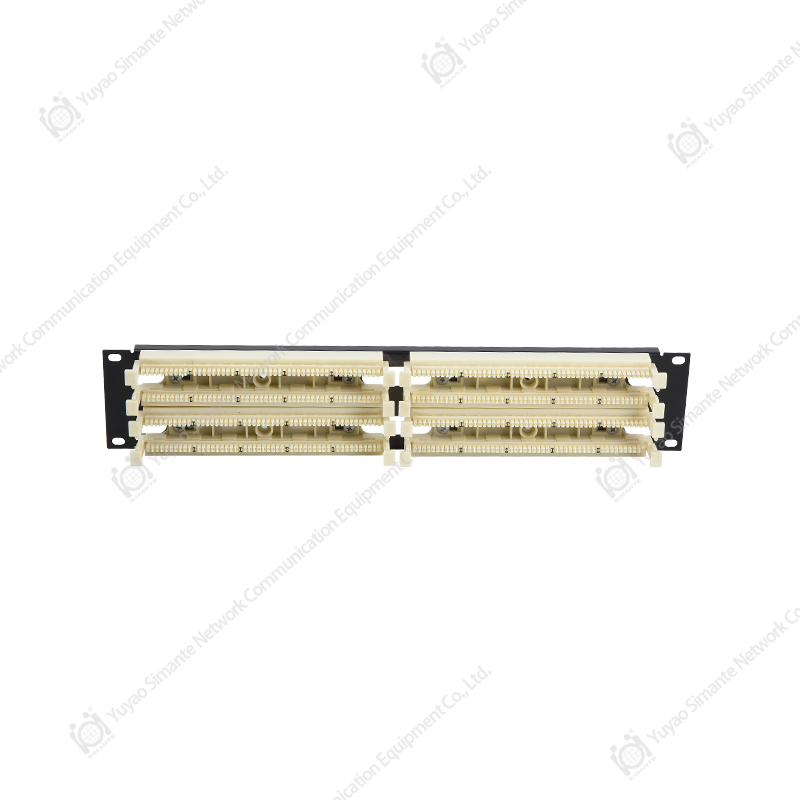
The product is a 19-inch rack-mount 110 distribution frame intended for flexible transfer, flexible distribution, and unified management of transmission signals. It supports enhanced 110 IDC wiring and is designed for use with compatible components from the same standards series. By bringing multiple cable termination and jumper management functions into an organized rack-mounted format, the wiring block helps installers and network administrators create cleaner, more manageable, and more adaptable communication infrastructure.
In a structured cabling environment, the same transmission medium may support voice, data, control, and other forms of information. The practical value of the SMT-3009D-200P lies in its ability to help connect and rearrange these services without repeatedly replacing the permanent horizontal or backbone cabling. Instead, changes can be managed through jumper connections between compatible patching and distribution components. This approach reduces disruption, supports future expansion, and makes the cabling system easier to maintain.
SMT-3009D-200P 110 Wiring Block
Product Overview
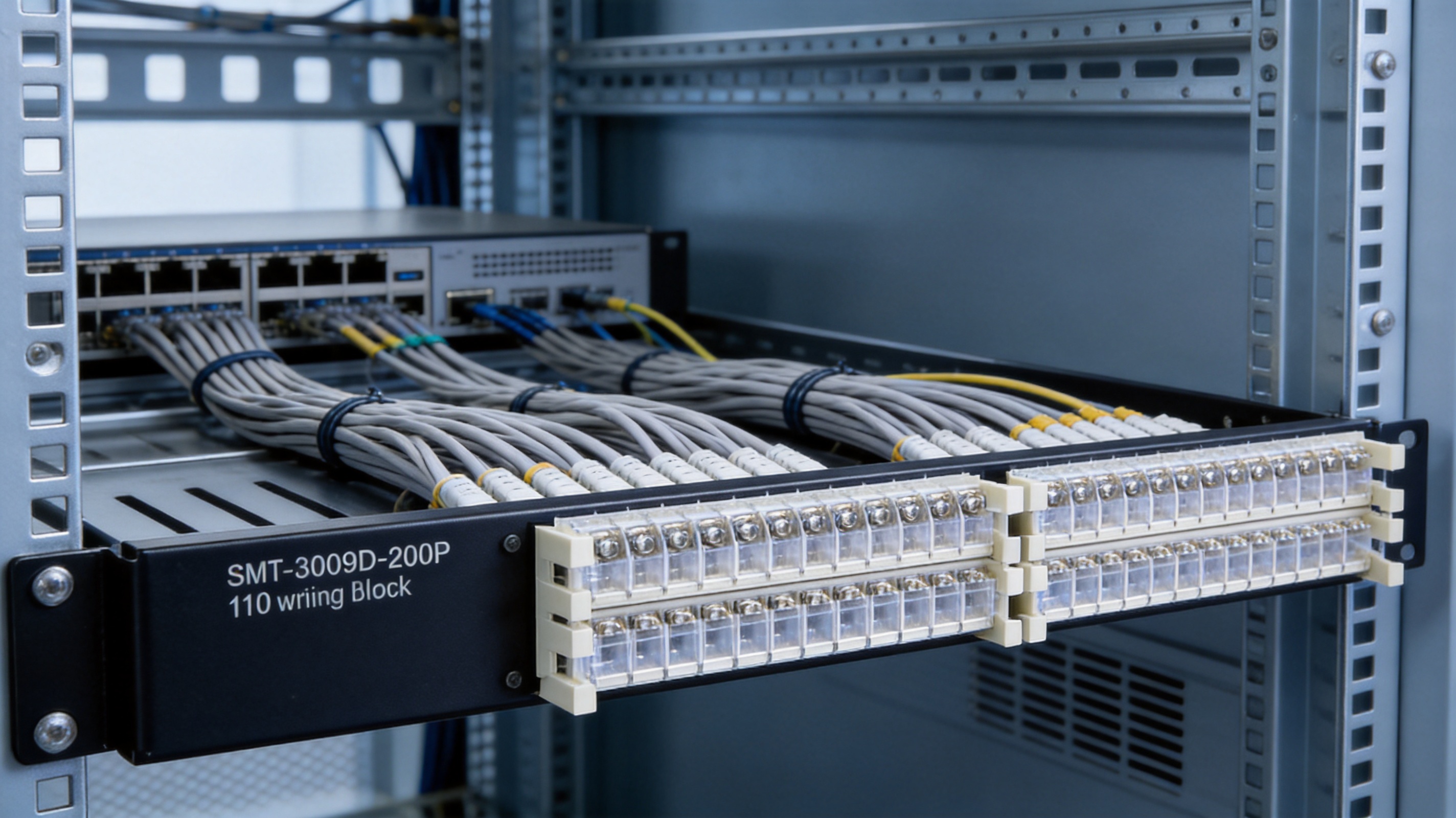
The SMT-3009D-200P 110 Wiring Block is a professional passive connectivity component for telecommunications rooms, equipment rooms, network cabinets, and structured cabling installations. Its rack-mount design conforms to the widely used 19-inch equipment format, allowing it to be installed in standard racks, cabinets, and suitable wall-mounted enclosures.
The unit is built around a robust metal bracket and an enhanced 110 IDC termination system. The bracket is manufactured from cold-rolled steel and finished with a protective plastic coating. This construction provides a stable mounting platform while helping protect the assembly from ordinary handling, installation wear, and environmental exposure. The IDC terminals are made from nickel-plated phosphor bronze, combining conductive performance with mechanical resilience and corrosion resistance.
The plastic components use PC polycarbonate. This material is widely used for electrical and telecommunications components because it offers a useful balance of dimensional stability, insulation performance, impact resistance, and manufacturability. The combination of a coated steel bracket, phosphor bronze IDC contacts, nickel plating, and polycarbonate insulation creates a practical assembly for repeated installation and service operations.
The wiring block is intended to clamp 23–26 AWG twisted-pair conductors. This range covers common telecommunications and structured cabling conductors used in building distribution systems. Installers can terminate compatible cables using the 110 IDC method without requiring a separate connector on every conductor. Once installed, the termination points can be managed through appropriate jumper connections and coordinated with other components in the structured cabling system.
Role in an Integrated Wiring System
The main purpose of an integrated wiring system is to provide a common, organized infrastructure through which different types of information can be transmitted. Instead of installing a separate and isolated cabling route for every application, a structured system uses planned cabling, standardized interfaces, distribution hardware, and patching methods to support multiple services.
A 110 distribution frame is an important part of this architecture. It provides a controlled termination point for multi-pair voice cables and other compatible conductors. It also supports the use of jumpers to establish or change connections between incoming cable pairs and the desired service or outlet. This makes the distribution frame more than a simple termination accessory. It becomes a practical management point for the entire low-voltage communication pathway.
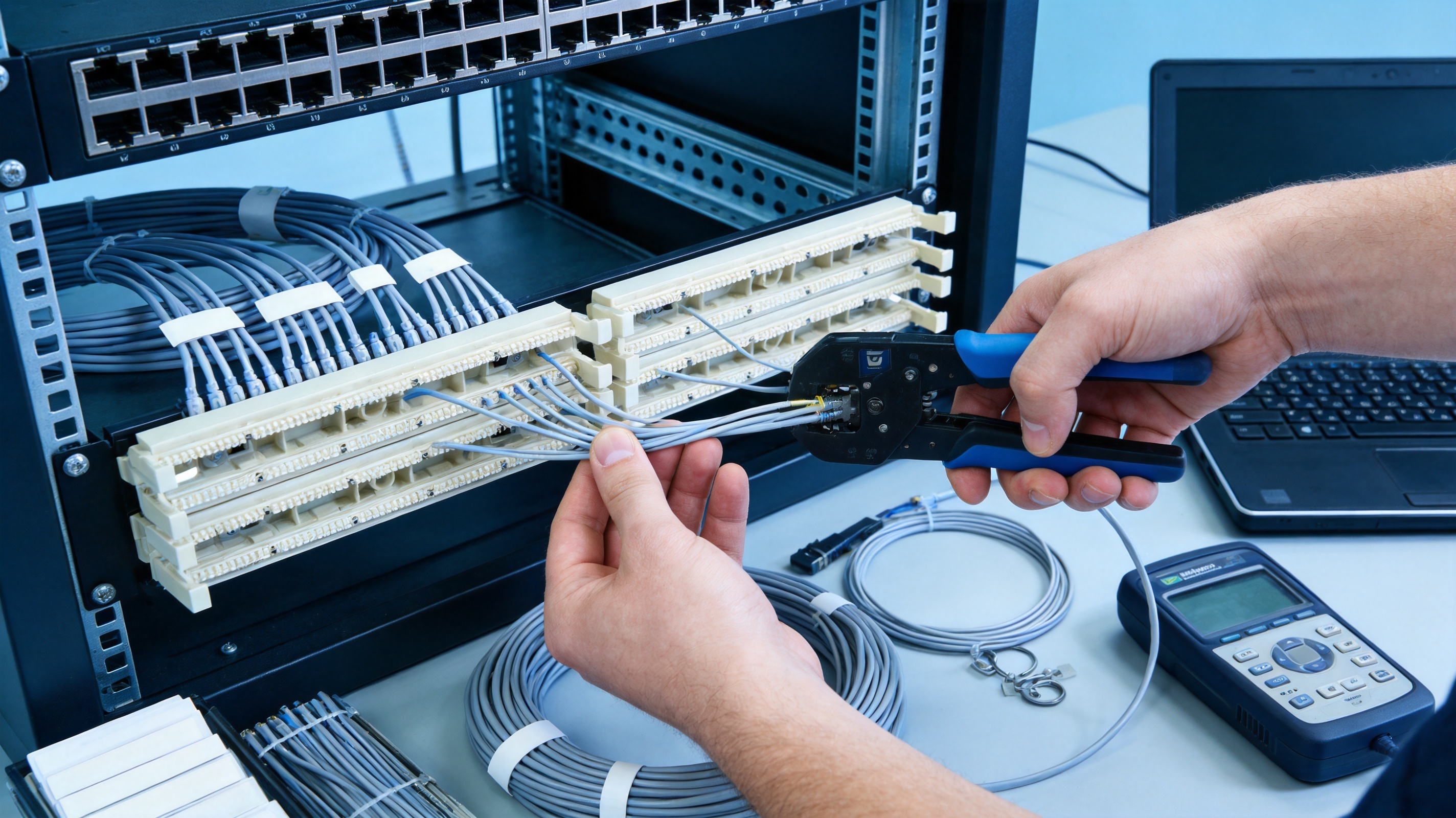
In a typical installation, horizontal twisted-pair cables from work areas may be terminated on RJ45 interface patch panels, while multi-pair voice cables from the main telephone room may be terminated on 110-style patching equipment. Jumper connections can then link the appropriate voice distribution points with compatible ports or patching assemblies. This arrangement allows the service function assigned to a desktop information point to be changed without replacing the fixed cable route.
The SMT-3009D-200P supports this flexible operating model. Its function is particularly valuable in buildings where office layouts change, tenants have different communication needs, or network and telephone services must be administered from a central location. A well-organized 110 block also helps technicians identify cable paths, isolate faults, perform moves and changes, and document the distribution system more efficiently.
Key Product Advantages
19-Inch Rack Compatibility
The standardized 19-inch mounting format is one of the most practical advantages of the product. Because 19-inch racks and cabinets are widely used in telecommunications and data communication rooms, installers can integrate the wiring block into existing infrastructure without designing a special enclosure.
Rack compatibility supports orderly installation. Equipment can be arranged by function, cable type, building zone, or service provider. When distribution components are mounted in a common rack, cable routes become easier to inspect and documentation can be coordinated with the physical layout. The rack-mounted structure also makes it easier to reserve space for future additions.
The product can be used with compatible equipment racks, cabinets, and wall-mount installations. This flexibility benefits projects with different room sizes and installation conditions. A large central equipment room may use several units in a full-height rack, while a smaller telecommunications closet may use a compact wall-mounted cabinet.
Enhanced 110 IDC Termination
The SMT-3009D-200P uses an enhanced 110 IDC wiring method. Insulation displacement connection technology is widely used in telecommunications because it allows conductors to be terminated directly into a contact slot. The termination process can be efficient, repeatable, and suitable for multi-pair cable management when performed with the correct tools and procedures.
The IDC terminal is specified for 23–26 AWG twisted-pair conductors. This compatibility gives installers a practical operating range for common copper communication cables. The design avoids unnecessary stripping and can help reduce termination time compared with some alternative connection methods. It also supports a compact arrangement of multiple pairs, which is important when space in a rack or telecommunications cabinet is limited.
Flexible Jumper-Based Distribution
A key benefit of a 110 wiring block is the ability to manage service connections through jumpers. Fixed cabling remains in place, while the active relationship between distribution points can be modified at the patching level. This is particularly useful for moves, additions, and changes.
For example, when a workstation changes location or a voice service must be reassigned, the technician may be able to modify the jumper arrangement rather than pull a new cable through walls, ceilings, or risers. This reduces installation disturbance and may lower the labor associated with routine administration. It also makes the network more adaptable to organizational change.
Durable Materials and Protective Finishes
The cold-rolled steel bracket provides structural support for the mounted assembly. Its plastic-sprayed surface treatment helps protect the metal from ordinary corrosion and handling damage. The nickel-plated phosphor bronze IDC terminals are selected for their combination of electrical conductivity, spring performance, and resistance to surface deterioration.
Polycarbonate insulation separates conductive elements and contributes to the mechanical stability of the termination area. PC is also valued for its impact resistance and dimensional consistency. These material choices help the wiring block maintain its functional geometry during installation and normal service.
Electrical Insulation and Withstand Performance
The product specification includes a dielectric withstand voltage of DC 1000 V, or AC 750 V, for one minute without breakdown or arcing. This requirement is relevant to the insulation system and helps demonstrate that the assembly can withstand a controlled electrical stress test.
The initial insulation resistance is specified as at least 1000 MΩ. High insulation resistance helps limit unwanted leakage between isolated conductive paths under appropriate test conditions. Together, the withstand voltage and insulation resistance specifications provide useful indicators of the product’s electrical insulation performance.
Repeated Termination Capability
The specified number of wire terminations is 250 times. This durability rating is important for distribution environments in which service points may be reworked, rearranged, or tested repeatedly during the operating life of a building.
Repeated termination capability supports the practical maintenance model of structured cabling. A telecommunications room is not static: users move, services change, and faults must be isolated. A connection system that tolerates repeated professional handling can help reduce the need for premature replacement of the entire distribution component.
Technical Specifications
| Item | Specification |
|---|---|
| Product model | SMT-3009D-200P |
| Product type | 110 Wiring Block |
| Mounting format | 19-inch rack-mount standard |
| Connection method | Enhanced 110 IDC wiring |
| Supported conductor range | 23–26 AWG twisted pair |
| Dielectric withstand voltage | DC 1000 V or AC 750 V for 1 minute |
| Initial insulation resistance | At least 1000 MΩ |
| Termination durability | Up to 250 wire terminations |
| Bracket material | Cold-rolled steel with plastic spray finish |
| IDC terminal material | Nickel-plated phosphor bronze |
| Insulating plastic | PC polycarbonate |
| Operating temperature specification | -25°C to +70°C |
| Humidity specification | Up to 85%, according to stated environmental requirements |
| Applicable general standard | YD/T 926.1-2009 |
| Applicable sub-standard | YD/T 926.3-2009 |
| Environmental compliance | RoHS requirements |
Advantages Compared with Less Flexible Distribution Methods
Different distribution methods may be suitable for different applications, but a structured 110 wiring block offers several practical advantages over informal splicing, unorganized terminal strips, or fixed point-to-point arrangements.
First, the rack-mounted format provides a defined location for cable termination. Unorganized cable joints can be difficult to identify and may make future work slow and error-prone. A structured wiring block establishes a repeatable physical layout, allowing technicians to label, inspect, and document connection points.
Second, jumper-based administration allows the service relationship to change without disturbing the permanent cable route. In a conventional fixed arrangement, even a minor change may require access to concealed cabling. With a distribution frame, many changes can be completed within the telecommunications room.
Third, the 110 IDC design supports efficient termination of multi-pair voice cables and compatible twisted-pair conductors. The compact arrangement can use cabinet space effectively, particularly when multiple cable pairs must be managed in a central location.
Fourth, the specified electrical and mechanical performance gives project designers measurable criteria for product selection. Withstand voltage, insulation resistance, conductor compatibility, and termination durability are more useful for engineering decisions than appearance alone.
Finally, standardized mounting and compatibility with same-series connectors help reduce uncertainty during installation. A coordinated product family can make it easier to plan accessories, jumper arrangements, labels, and replacement components.
Manufacturing Strengths and Quality Approach
The manufacturer behind the product integrates design, development, sales, and service for network cabling solutions and optical fiber products. This integrated structure is valuable because a passive connectivity component must be considered from several perspectives at once. Product geometry, mold design, materials, assembly, packaging, installation practice, and field service all influence the final result.
The company reports a mature research and development system supported by more than ten engineers and over thirty full-time technical personnel. A dedicated technical team can contribute to product improvement, production troubleshooting, tooling refinement, and customer-specific development. This is especially important for structured cabling components, where small changes in contact geometry, plastic dimensions, or assembly tolerances can influence installation quality.
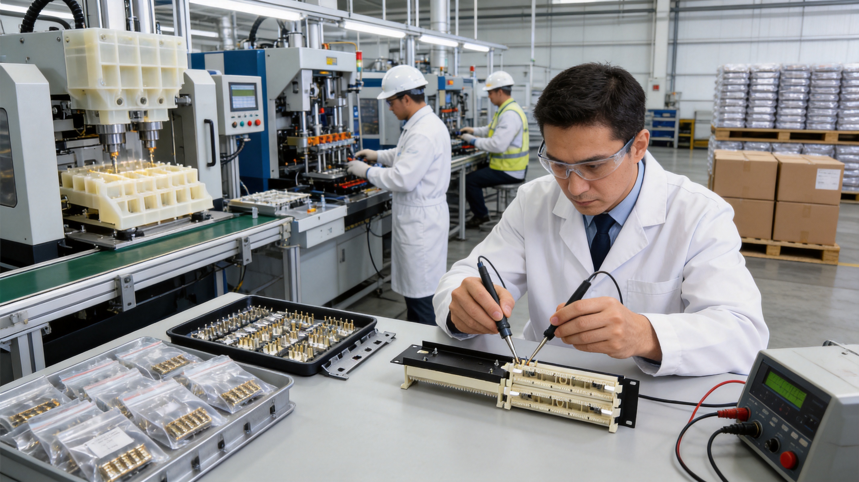
The production operation includes ten regular and customization production lines, ten fully automatic injection molding machines, twenty semi-automatic injection molding machines, and eight automatic installation machines. This combination of automated and semi-automated equipment provides manufacturing flexibility.
Automatic injection molding equipment can improve repeatability for polycarbonate and other molded components by controlling material delivery, mold filling, cooling, and cycle conditions. Consistent molding is important for IDC products because dimensional accuracy affects alignment, insulation separation, and assembly fit.
Semi-automatic equipment can support product variants, smaller production runs, and customized requirements. It can also provide flexibility when different customer specifications require changes in labeling, packaging, mounting details, or assembly configurations. The coexistence of automatic and semi-automatic processes allows the manufacturer to balance efficiency with customization.
Automatic installation machines can support repeatable assembly of contacts and other components. Consistent insertion depth, positioning, and assembly pressure may help reduce variation between production batches. Automation also enables production personnel to focus more closely on process monitoring, inspection, material control, and final verification.
The manufacturer states that its factory maintains an annual output of more than nine million units. This production capacity indicates the ability to support volume projects while maintaining a stable supply program. For contractors, distributors, system integrators, and OEM customers, reliable production capacity can be as important as the individual product specification.
Manufacturing strength is not limited to equipment count. A complete quality approach also includes incoming material control, production process management, dimensional inspection, electrical testing, mechanical verification, and packaging checks. Each stage protects a different aspect of product performance.
Material Control
Material control begins with verifying the quality and suitability of steel, phosphor bronze, nickel plating materials, polycarbonate resin, and protective coatings. The specified materials must be consistent with the intended electrical, mechanical, and environmental performance.
For IDC terminals, the contact material and plating condition are especially important. The terminal must maintain appropriate contact pressure and provide a stable conductive interface after termination. For molded parts, resin quality and molding conditions influence insulation performance, strength, and dimensional accuracy.
Precision Molding
The polycarbonate components require controlled molding conditions. Mold temperature, injection pressure, cooling time, and material drying can influence the final part. Stable production parameters help limit warpage, surface defects, dimensional variation, and incomplete filling.
Precision molding also supports assembly efficiency. When plastic components maintain consistent dimensions, they can align more accurately with metal contacts and brackets. This can reduce assembly adjustment and support predictable performance during inspection.
Contact and Assembly Processing
The IDC contact assembly must be positioned correctly so that conductors can be terminated consistently. Automatic installation equipment can help control the placement of contacts and related components. Assembly inspection may verify that contacts are seated correctly, that insulation barriers are present, and that no conductive parts are damaged.
The metal bracket and surface finish must also be inspected. The bracket needs to provide stable mounting holes and sufficient rigidity for rack installation. The plastic coating should be continuous and suitable for the intended handling and environmental conditions.
Performance Testing
Testing is a central part of a professional passive component manufacturing process. Electrical tests can verify insulation resistance and dielectric withstand performance. Mechanical checks can confirm conductor compatibility, contact retention, mounting stability, and termination durability.
Environmental assessment may include temperature and humidity exposure, material evaluation, and salt spray testing. The product information specifies a salt solution with a pH value between 6.5 and 7.2 before atomization at 35 ± 2°C. The solution uses sodium chloride at a concentration of 5 ± 0.1 percent by mass, prepared with distilled or deionized water. Continuous atomization is recommended for 24 hours while protecting the test environment from oil, dust, and other interfering impurities.
These test conditions help evaluate the resistance of exposed metal and treated surfaces to a controlled corrosive atmosphere. They do not replace project-specific environmental engineering, but they provide a structured method for checking material and finish performance.
Standards and Compliance Considerations
The product information identifies YD/T 926.1-2009 as the applicable general specification and YD/T 926.3-2009 as the applicable sub-standard. These references provide a framework for evaluating telecommunications wiring components and their application within a structured system.
The product is also specified to meet RoHS requirements. Restriction of hazardous substances is increasingly important for international procurement, environmental management, and responsible electronics and telecommunications manufacturing. RoHS-related compliance supports customers that need to align their supply chain with restricted-material requirements.
Standards compliance should always be considered together with the complete project design. A wiring block is only one part of a structured cabling installation. Cable category, patch panels, connectors, grounding, separation from power circuits, bend radius, labeling, and installation workmanship all influence final system performance.
For this reason, the SMT-3009D-200P should be installed with connectors and accessories from the same standard series or with components confirmed to be compatible by the system designer. Matching components helps ensure that conductor sizes, termination geometry, contact spacing, and operating procedures are properly coordinated.
Installation and Administration Recommendations
Planning the Rack Layout
Before installation, the rack should be planned according to cable routes, service zones, future capacity, and access requirements. The wiring block should be positioned so that incoming cables can be routed without excessive bending or strain. Space should be reserved for jumpers, labels, service loops, and future changes.
A clear rack layout makes maintenance faster. Equipment should be arranged in a logical order, such as by floor, building section, tenant, service type, or cable number. The physical arrangement should correspond to the project documentation.
Preparing the Cable
Only compatible 23–26 AWG twisted-pair conductors should be terminated. Cable jackets should be removed carefully, leaving sufficient support near the termination area. Excessive untwisting of twisted pairs should be avoided because maintaining pair geometry supports signal integrity.
Installers should use the recommended IDC termination tool and follow the applicable wiring scheme. Conductors should be seated fully in the correct slots, and excess wire should be trimmed cleanly. Each pair should be checked for correct placement before the panel is placed into service.
Labeling and Documentation
Every cable and termination point should be labeled according to the project numbering system. Labels should be durable, readable, and consistent with drawings or electronic records. A wiring block can only provide efficient management when technicians can identify the source, destination, service, and status of each connection.
Documentation should record jumper changes, service assignments, cable tests, and maintenance activities. This information reduces the risk of accidental disconnection and shortens the time required for future troubleshooting.
Jumper Management
Jumpers should be routed neatly and should not obstruct access to termination points. They should have enough slack for service work but should not be so loose that they become tangled. Different colors or labeling conventions may be used to distinguish voice, data, security, control, or other services when permitted by the project specification.
Before changing a jumper, technicians should confirm the circuit identity and service authorization. After the change, the connection should be tested and the documentation updated. This controlled process helps prevent unintended service interruption.
Applications
The SMT-3009D-200P can support a range of structured copper cabling applications.
Commercial Office Buildings
Office buildings frequently experience changes in tenant layouts, workstations, telephone assignments, and network services. A centralized 110 distribution frame gives facility and network teams a practical location for administering voice and compatible copper connections.
Telecommunications Rooms
Telecommunications rooms require compact, organized, and serviceable termination hardware. The rack-mount design allows multiple distribution units to be arranged in a standardized cabinet while maintaining access for testing and changes.
Educational Facilities
Schools, colleges, and training centers may have constantly changing room assignments and communication requirements. Flexible jumper-based distribution can simplify the reassignment of services between classrooms, offices, laboratories, and shared spaces.
Hotels and Hospitality Facilities
Hotels and similar facilities contain a large number of rooms and service areas. A structured distribution system can help centralize administration for voice and communication connections while supporting renovations and changes in room use.
Industrial and Commercial Campuses
Large campuses often include several buildings, departments, and communication zones. Properly organized distribution frames can support consistent cabling administration across multiple telecommunications rooms and provide a documented connection point for each service area.
OEM and Customized Projects
The manufacturer’s combination of standard production lines and customization capacity makes the product family suitable for OEM and ODM programs. Customers may require special labels, packaging, documentation, accessory combinations, or project-specific configurations. Any customization should be reviewed against the required electrical, mechanical, environmental, and standards criteria.
Packaging, Storage, and Logistics
The product is placed in a dedicated blister bag and then packed in a cardboard box. Product accessories are placed with the unit, and a label indicating the product model and quantity is affixed to the upper-left area of the carton front. This packaging arrangement helps protect the wiring block during handling and provides basic identification during warehouse operations.
The standard packing information indicates ten individual boxes per outer carton, with one product per individual box and ten products per outer carton. Customer-specified packaging is also available as a product-use option. Project buyers should confirm the final packing configuration before shipment, especially when special labels, palletization, or export documentation is required.
Packaged products should be stored in a warehouse with an ambient temperature of -5°C to +30°C and relative humidity not exceeding 70 percent. The surrounding air should be free of acid, alkali, and other corrosive gases. Under the stated conditions, the storage period is three years.
During transportation and storage, cartons should be kept dry and protected from impact, compression, direct contamination, and prolonged exposure to extreme temperatures. The product should remain in its original packaging until installation whenever practical. Proper storage helps preserve the metal finish, molded insulation parts, labels, and accessory contents.
Why Manufacturing Capability Matters to Buyers
For a passive cabling component, manufacturing capability directly affects project confidence. A wiring block may appear simple, but it contains several interfaces that must work together: the rack bracket, insulated body, IDC contacts, mounting points, labeling area, and cable termination geometry.
Large-scale production experience can help a manufacturer identify recurring process issues and improve product consistency. A stable manufacturing platform also supports repeat orders, replacement availability, and consistent product appearance across different project phases.
Engineering resources are important when customers need assistance selecting compatible components or adapting a product to a specific installation. Technical personnel can help evaluate cable types, mounting conditions, packaging requirements, and project documentation. For OEM and ODM customers, engineering support can also shorten the path from concept to production.
Quality testing provides another important advantage. Production volume alone does not guarantee performance, but production capacity combined with documented inspection and testing creates a stronger basis for reliable supply. Electrical, mechanical, material, and environmental checks should be considered part of the complete manufacturing value offered to the customer.
Selection Guidance for Project Designers
When selecting a 110 wiring block, project designers should first confirm the required cable type and conductor gauge. The SMT-3009D-200P is specified for 23–26 AWG twisted-pair conductors. The selected cable should fall within this range and should be suitable for the intended service.
The designer should then confirm rack or cabinet compatibility. The 19-inch mounting format is widely used, but the available depth, mounting rails, cable entry direction, and surrounding equipment must still be checked. Sufficient working space should be provided for termination tools and future maintenance.
Compatibility with patch panels, connectors, jumpers, and other distribution components should also be verified. Using components from the same standard series can reduce installation uncertainty and improve the consistency of the complete system.
Environmental conditions should be reviewed before ordering. The stated operating temperature range is -25°C to +70°C, while storage conditions are more limited. Locations with unusual chemical exposure, high condensation, dust, salt, or extreme humidity may require additional enclosure and environmental protection measures.
Finally, buyers should define packaging, labeling, inspection, and documentation requirements in advance. These details can be particularly important for multi-site projects, export shipments, and OEM programs.
Maintenance and Service Benefits
Once installed, the SMT-3009D-200P can help simplify routine maintenance. Technicians can inspect termination points, trace jumpers, test pairs, and make approved changes from a central location. The rack-mounted structure provides a consistent reference point for service documentation.
Periodic inspections should check for loose mounting hardware, damaged cables, incorrect labels, excessive jumper congestion, and signs of corrosion or contamination. Any connection that has been modified should be tested and recorded according to the site maintenance procedure.
Because the product is specified for up to 250 wire terminations, it is suitable for environments where professional rework may occur over time. However, the durability rating does not eliminate the need for correct tools and technique. Repeated work should always be performed carefully to avoid conductor damage, contact deformation, or insulation disturbance.
Good maintenance also includes keeping the telecommunications room clean and dry. Dust, oil, moisture, and corrosive gases can affect passive components and cable interfaces. Proper rack ventilation and access control can further protect the installation.
Q&A
What is the SMT-3009D-200P used for?
The SMT-3009D-200P is a 110 wiring block used to terminate and manage compatible twisted-pair and multi-pair communication cables. It supports flexible distribution and jumper-based administration in structured copper cabling systems.
Is the product suitable for a standard equipment rack?
Yes. The product uses a 19-inch rack-mount format and is designed to be compatible with standard 19-inch equipment racks, cabinets, and suitable wall-mounted enclosures.
What type of connection method does it use?
It uses an enhanced 110 IDC wiring method. The IDC terminals are specified for 23–26 AWG twisted-pair conductors.
Can it be used with RJ45 patch panels?
The wiring block is intended primarily for 110-style termination and distribution. In a complete structured cabling system, it may be used alongside RJ45 patch panels when the interfaces, wiring practices, and application requirements are properly matched.
What materials are used in the product?
The bracket is made from cold-rolled steel with a plastic spray finish. The IDC terminals use nickel-plated phosphor bronze, and the insulating plastic components use PC polycarbonate.
How many times can the wiring points be terminated?
The specified termination durability is 250 wire terminations. Professional tools and correct installation procedures should be used to achieve the rated performance.
What are the main electrical specifications?
The product is specified for a withstand voltage of DC 1000 V or AC 750 V for one minute without breakdown or arcing. Its initial insulation resistance is specified as at least 1000 MΩ.
Does the product meet environmental requirements?
The product information states that it meets RoHS requirements. It also specifies an operating temperature range of -25°C to +70°C and includes salt spray test conditions for evaluating resistance to a controlled corrosive environment.
What standards are referenced?
The stated applicable standards are YD/T 926.1-2009 as the general specification and YD/T 926.3-2009 as the sub-standard. Project designers should verify the complete system requirements before installation.
How should the product be stored?
Packaged products should be stored at -5°C to +30°C, with relative humidity not exceeding 70 percent, in an area free from acid, alkali, and other corrosive gases. The stated storage period is three years under these conditions.
Can customized packaging be provided?
Yes. The product information identifies customer-specified packaging as an available option. Packaging details, labels, quantities, and export requirements should be confirmed with the supplier before production or shipment.
What manufacturing support is available?
The manufacturer has engineering, technical, injection molding, assembly, and production capabilities for standard and customized network cabling products. It reports multiple regular and customization production lines, automated and semi-automated injection molding equipment, and automatic installation machinery.
Conclusion
The SMT-3009D-200P 110 Wiring Block is designed to provide an organized, flexible, and durable termination platform for structured copper cabling systems. Its 19-inch rack-mount format supports integration into standard equipment rooms and cabinets, while the enhanced 110 IDC method provides an efficient way to terminate compatible 23–26 AWG twisted-pair conductors.
Its principal advantages include jumper-based flexibility, standardized rack compatibility, repeatable cable administration, durable metal and plastic materials, specified electrical insulation performance, and a termination durability rating of up to 250 wire terminations. These features make it suitable for telecommunications rooms, commercial buildings, educational facilities, hospitality sites, industrial campuses, and other installations where communication services must be organized and adaptable.
The product is also supported by a manufacturer with integrated design, development, production, sales, and service capabilities. Engineering personnel, automated injection molding, semi-automated production, automatic installation equipment, customization lines, and reported annual output exceeding nine million units provide a strong foundation for standard supply and OEM or ODM cooperation.
For customers planning a structured cabling project, the value of the SMT-3009D-200P extends beyond the individual wiring block. It contributes to a complete approach to signal distribution in which permanent cabling, standardized interfaces, clear documentation, and controlled jumper changes work together. When installed with compatible components and maintained according to professional procedures, it can help create a cleaner, more serviceable, and more future-ready communication infrastructure.
References
1. YD/T 926.1-2009, General Specification for Telecommunications Cabling Components and Related Structured Cabling Applications.
2. YD/T 926.3-2009, Applicable Sub-Standard for Telecommunications Cabling Components.
3. TIA/EIA Structured Telecommunications Cabling Standards, including requirements related to horizontal cabling, termination, administration, and telecommunications spaces.
4. ISO/IEC Structured Cabling Standards for Generic Cabling Systems in Customer Premises.
5. RoHS Requirements for the Restriction of Hazardous Substances in Electrical and Electronic Equipment.
6. Product technical information for the SMT-3009D-200P 110 Wiring Block, including electrical, mechanical, environmental, material, packaging, and storage specifications.