Español
 عربى
عربى русский
Content
- 1 Product Overview and Application Scope
- 2 Key Product Advantages
- 3 Electrical and Mechanical Characteristics
- 4 Materials and Surface Treatment
- 5 Installation and Termination Guidance
- 6 Advantages Over Basic or Poorly Designed Patch Panels
- 7 Manufacturing Strengths and Quality-Oriented Production
- 8 Environmental and Reliability Considerations
- 9 Packaging, Logistics, and Project Procurement
- 10 Typical Use Cases
- 11 Recommended Project Selection Criteria
- 12 Maintenance and Long-Term Service
- 13 Q&A
- 13.1 What is the SMT-2026H24C6 patch panel used for?
- 13.2 How many ports does the panel provide?
- 13.3 Is the panel compatible with standard 19-inch racks?
- 13.4 Does it support both T568A and T568B?
- 13.5 What type of termination does it use?
- 13.6 What does the 180-degree design mean in practical terms?
- 13.7 What is the operating frequency range?
- 13.8 Can the patch panel be used for outdoor installations?
- 13.9 What materials are used in the product?
- 13.10 How does the product help reduce installation time?
- 13.11 What testing should be performed after installation?
- 13.12 Does the manufacturer support customized projects?
- 13.13 What is the standard packaging quantity?
- 14 Conclusion
- 15 References
- 16 Product: SMT-2026H24C6 1U24 Port 180 Degree CAT6 UTP Patch Panel
Modern communication networks depend on organized, reliable, and serviceable cabling infrastructure. Although active devices such as switches, routers, wireless controllers, and servers receive much of the attention in a network installation, passive connectivity products are equally important to long-term performance. A poorly designed termination point can create intermittent faults, excessive crosstalk, difficult maintenance, and unnecessary installation time. The SMT-2026H24C6 1U 24-Port 180-Degree CAT6 UTP Patch Panel is designed to address these challenges by combining Category 6 performance, compact rack utilization, clear port identification, dependable IDC termination, and practical cable management in one professional-grade product.
This 24-port patch panel is intended for structured cabling systems that use unshielded twisted-pair copper cable. It provides a centralized termination and cross-connection point between horizontal cabling, equipment connections, and work-area outlets. Its 1U format is compatible with standard 19-inch racks, cabinets, and selected wall-mount applications, allowing installers to integrate it into telecommunications rooms, server rooms, data centers, offices, educational facilities, commercial buildings, and other network environments.
The 180-degree port and termination arrangement supports a neat and accessible installation layout. The front of the panel provides 24 RJ45 ports with identification labels, while the rear includes IDC termination points and a cable management structure intended to guide conductors toward their correct termination locations. By bringing together clear labeling, standardized wiring, robust materials, and tested electrical and mechanical characteristics, the product offers a practical alternative to lower-quality patch panels that may be difficult to terminate or maintain.
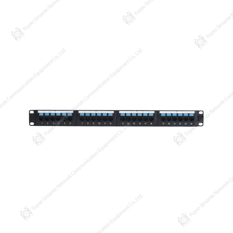
SMT-2026H24C6 1U24 Port 180 Degree CAT6 UTP Patch Panel
Product Overview and Application Scope
The SMT-2026H24C6 is a Category 6 UTP patch panel with 24 ports arranged in a 1U rack-mount chassis. It is designed to meet Category 6 transmission requirements and to support T568A and T568B wiring sequences. These wiring options allow installers to follow the cabling practices required by the project, provided that the same wiring standard is maintained consistently across the link.
The patch panel serves as an interface between two important sections of a structured cabling network. The first is the horizontal cabling system, which carries connections from the telecommunications room toward work areas, equipment zones, or outlet locations. The second is the equipment or work-area connection, which commonly uses short patch cords to connect the terminated ports to active network equipment. The patch panel creates an organized transition between these sections and reduces the need to terminate horizontal cables directly into switching equipment.
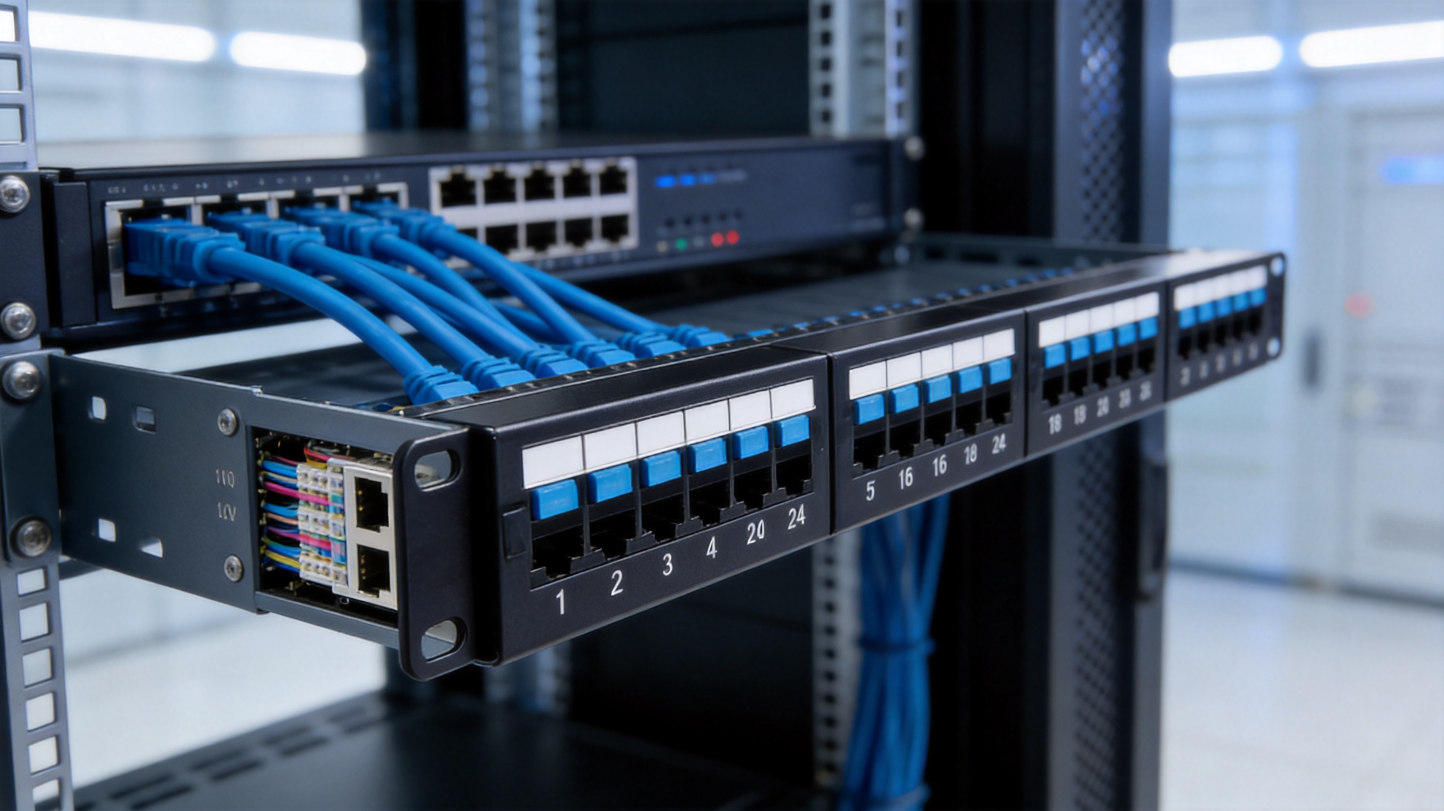
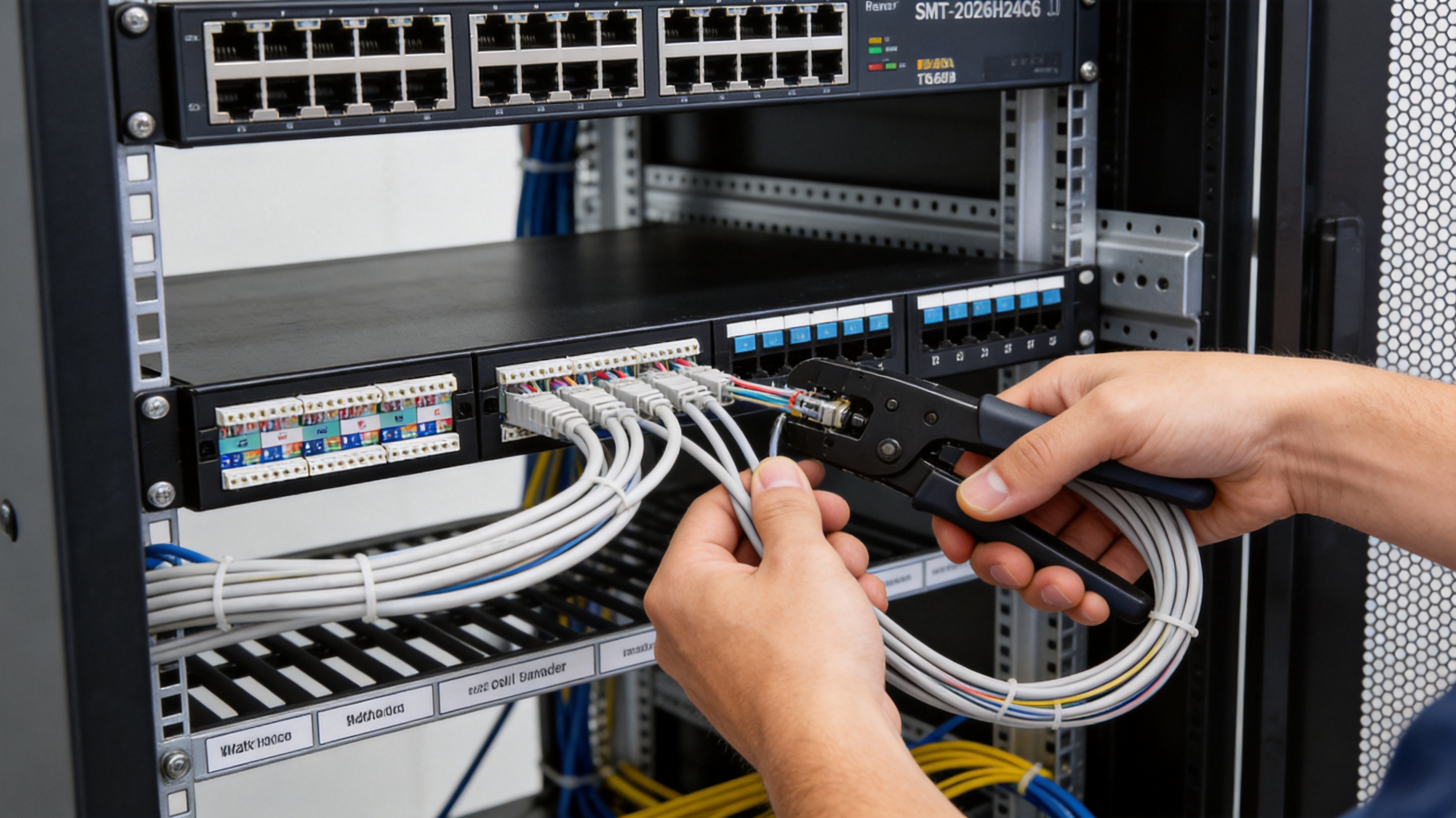
In a typical installation, permanent horizontal cables are routed into a rack or cabinet and terminated on the rear of the panel using IDC technology. Short RJ45 patch cords are then connected to the front ports and routed to network switches or other equipment. This arrangement protects the permanent cable terminations from repeated handling and makes network changes easier to perform. If a device is moved or a switch port is changed, the technician can generally modify the front patching arrangement without disturbing the building’s permanent cabling.
The product is suitable for copper structured cabling systems in commercial offices, industrial control areas, schools, hospitals, hotels, retail sites, public buildings, and residential or smart-home projects requiring centralized network distribution. It can also be used in equipment rooms and communications enclosures where a high port density is needed without consuming more than one rack unit of vertical space.
Key Product Advantages
Category 6 Transmission Performance
The primary advantage of this patch panel is its alignment with Category 6 transmission requirements. Category 6 systems are designed for higher-frequency performance than earlier Category 5e installations, supporting modern Ethernet applications when the entire channel—including cable, connectors, patch cords, and installation practices—is correctly specified and installed.
The panel supports a frequency range of 1 to 250 MHz. This frequency capability is important because Category 6 performance depends not only on the physical connection but also on maintaining suitable signal integrity across the operating range. The connector design, contact arrangement, PCB construction, and termination structure all contribute to the quality of the connection.
The product uses a contact-pin arrangement based on high-and-low dislocation technology. This design helps reduce near-end crosstalk by increasing separation between contact paths and controlling the interaction between adjacent pairs. Reduced crosstalk is especially important in a 24-port panel because many high-speed connections are installed in close proximity. A compact product must maintain electrical separation even when ports are densely arranged.
Efficient 1U Rack Utilization
Rack space is valuable in telecommunications rooms and data centers. A 1U product can provide 24 copper ports while preserving vertical space for switches, cable managers, fiber enclosures, power distribution units, or future expansion. The standard 19-inch rack-mount format makes the panel compatible with widely used cabinets and equipment racks.
The sturdy metal bracket is manufactured from cold-rolled steel and finished with a protective plastic coating. This construction provides a firm mounting platform and helps the product withstand normal installation, patching, and maintenance activities. Compared with lightweight or poorly supported panels, a rigid bracket can reduce movement during cable termination and help preserve alignment after installation.
Clear Front-Port Identification
Each of the 24 front ports includes identification space, and the large front label area provides additional room for customer-defined port marking. Proper labeling is one of the most effective ways to reduce troubleshooting time. A clearly identified port allows a technician to trace a connection from the rack to the work area without repeatedly testing or disconnecting neighboring cables.
For larger structured cabling projects, labels can identify room numbers, outlet numbers, switch ports, rack positions, VLAN groups, or other project-specific information. The panel’s labeling arrangement supports a consistent documentation method and makes future moves, additions, and changes easier to manage.
Rear Cable Guidance
The rear cable manager is designed to guide cables toward their termination points. Cable guidance is particularly useful in a 24-port panel because the cable bundle can become crowded during installation. A controlled routing path helps maintain a clean termination field, reduces the risk of accidental cable strain, and makes it easier to identify individual pairs.
Good cable management also supports bend-radius control. Twisted-pair cables contain carefully balanced conductors, and excessive bending, sharp pressure, or uncontrolled pulling can affect transmission performance. A suitable rear support structure helps installers route cables with less mechanical stress and supports a cleaner final installation.
IDC Termination for Permanent Cabling
The panel uses 110-type IDC termination technology. IDC terminals connect the conductors by placing them into slots that make contact through the insulation displacement process. This method is widely used in structured cabling because it provides a repeatable termination approach without requiring the installer to strip each conductor individually.
The IDC terminal accommodates 23 to 26 AWG twisted-pair cable. This range covers common permanent-link cable sizes used in Category 6 installations. The wiring area is marked for standard line sequences, helping installers terminate pairs according to T568A or T568B requirements. Correct pair placement and consistent termination are essential to preserve polarity, pair balance, and overall channel performance.
IDC termination is also well suited to permanent cabling because the rear connection is not normally disturbed after installation. Front-facing RJ45 ports can be patched and repatched as network requirements change, while the IDC terminations remain stable and protected at the back of the panel.
Durable Connection System
The product is designed for repeated operational use. The specified insertion and withdrawal durability of the plug-and-socket interface is 750 cycles, while the specified number of wire terminations is 250 cycles. These values indicate that the connector and termination structures are intended for professional installations where service activity may occur over the life of the network.
The insertion force is specified at no more than 20 N, and the pull-out force is specified at no less than 20 N. These characteristics seek to balance ease of connection with resistance to accidental cable removal. A connector that is too loose may disconnect during maintenance or vibration, while a connector that requires excessive force can increase installation difficulty and place stress on the plug or jack.
Electrical and Mechanical Characteristics
The SMT-2026H24C6 combines electrical specifications with mechanical features intended for reliable field installation. The electrical design includes a working voltage of 125 V, a withstand-voltage test of DC 1000 V or AC 750 V for one minute without breakdown or arcing, and an initial insulation resistance of at least 100 MΩ. After a constant damp-heat test, the specified insulation resistance remains at least 100 MΩ.
These values are relevant to the safety and stability of the connection structure. High insulation resistance helps limit unwanted current leakage between conductive elements, while withstand-voltage testing verifies that the insulation system can tolerate a defined electrical stress under controlled test conditions. As with any passive network component, the patch panel must be installed and operated within the requirements of the complete cabling system.
The specified near-end crosstalk attenuation is at least 4 dB according to the provided product information. Crosstalk is the unwanted coupling of signal energy from one pair or circuit into another. In a dense patch panel, contact layout, printed circuit board routing, pair separation, and connector geometry all influence crosstalk behavior. The high-and-low dislocation contact structure is intended to improve separation and reduce near-end interference between adjacent contacts.
Mechanical performance is also essential. The connector connection device is specified to withstand a 50 N force for 60 ± 5 seconds. This type of test evaluates the strength of the connection structure under a defined load. The cold-rolled steel bracket adds support for rack installation, while the combination of PC polycarbonate and ABS plastics provides a balance of structural strength, electrical insulation, and molding flexibility for the non-metallic components.
| Item | Specification | Installation Benefit |
|---|---|---|
| Product type | Category 6 UTP patch panel | Supports organized copper structured cabling |
| Port count | 24 RJ45 ports | High port density for a 1U rack position |
| Rack format | 19-inch, 1U standard | Compatible with common cabinets and equipment racks |
| Port orientation | 180-degree layout | Supports practical front and rear cable routing |
| Frequency range | 1–250 MHz | Aligned with Category 6 transmission requirements |
| Wiring method | 110-type IDC termination | Suitable for permanent horizontal cabling |
| Supported conductor size | 23–26 AWG twisted pair | Compatible with common Category 6 cable sizes |
| Wiring sequences | T568A and T568B | Allows project-standard termination practices |
| Front identification | Individual port labels and large label area | Improves traceability and maintenance efficiency |
| Rear organization | Integrated cable manager | Guides cables toward termination points |
| Connector durability | 750 insertion and withdrawal cycles | Supports repeated patching and servicing |
| Wire termination durability | 250 termination cycles | Supports installation and maintenance requirements |
| Operating temperature | -25°C to +70°C | Suitable for a broad range of indoor environments |
| Humidity requirement | Up to 85% as specified | Supports use in controlled telecommunications spaces |
| Environmental compliance | RoHS | Supports material-restricted project requirements |
Materials and Surface Treatment
Material selection directly affects the service life and performance of a patch panel. The bracket is made from cold-rolled steel with a plastic spray finish. Cold-rolled steel provides the rigidity required for rack mounting, while the surface finish helps protect the metal from routine handling and environmental exposure.
The gold needle is made from phosphor bronze with gold plating. Phosphor bronze is commonly selected for connector contacts because it offers suitable spring characteristics and electrical conductivity. Gold plating helps provide a stable contact surface and can reduce the impact of oxidation at the mating interface. The specified gold-plating thickness is 6–50U according to the supplied technical information.
The IDC card-wire terminal uses nickel-plated phosphor bronze. This material combination supports resilient contact behavior during termination while providing a protective surface finish. IDC terminals must maintain effective contact with the conductor after the insulation displacement process, and their geometry must remain stable during installation.
The plastic components use PC polycarbonate and ABS. Polycarbonate contributes impact resistance and dimensional stability, while ABS is widely used for molded connector housings and structural components because of its processing characteristics and balanced mechanical performance. The PCB uses FR4 material, a common glass-reinforced epoxy laminate used for printed circuit boards in communications equipment.
The combination of steel, phosphor bronze, gold, nickel, PC, ABS, and FR4 reflects a multi-material design approach. Each material is assigned to a function suited to its characteristics: mechanical support, electrical contact, corrosion resistance, insulation, housing protection, or circuit-board stability.
Installation and Termination Guidance
Correct installation is essential to achieving the expected performance of any Category 6 patch panel. The installer should first confirm that the rack, cabinet, or wall-mount structure is suitable for a standard 19-inch, 1U component. The panel should be mounted securely using appropriate rack hardware, with enough rear clearance for cable routing and termination.
Before terminating cables, the installer should identify each permanent cable according to the project drawings. Cable labels should be applied before the conductors are placed into the IDC terminals. This practice reduces the risk of mixing cables and simplifies verification after the termination work is complete.
The cable jacket should be removed only as far as necessary to place the conductors into the termination area. Excessive untwisting can affect pair balance and transmission performance. The individual pairs should remain twisted as close as practical to the IDC termination point. The installer should follow the selected T568A or T568B sequence and use the same sequence at the corresponding outlet or connector.
Conductors should be placed fully into the correct IDC slots and terminated with an appropriate 110-style punch-down tool. The termination should be firm and visually inspected for incomplete seating, stray conductor strands, incorrect pair placement, or damage to the cable jacket. The rear cable manager should then be used to maintain an orderly cable path and avoid unnecessary tension on the IDC points.
After termination, each link should be tested with suitable copper certification or verification equipment. Testing may include wire map, continuity, length, insertion loss, return loss, near-end crosstalk, and other parameters required by the project. A patch panel cannot compensate for poor-quality cable, excessive untwisting, incorrect termination, or improper routing, so the entire permanent link and channel should be considered during acceptance testing.
T568A and T568B Compatibility
The panel supports both T568A and T568B line sequences. These are recognized wiring arrangements for eight-position, eight-contact modular connectors. The choice between them is generally determined by the project standard, existing infrastructure, local practice, or customer specification.
The critical requirement is consistency. If one end of a permanent link uses T568A and the other end uses T568B, the result may be a crossover arrangement rather than a standard straight-through connection. In modern network equipment, automatic crossover capabilities may allow some links to operate, but structured cabling installations should still follow a consistent and documented wiring plan.
Color labels on the panel assist the installer in identifying the required conductor locations. Clear markings reduce termination errors and support faster work, especially when multiple panels are installed in the same rack or when cables from different zones arrive at the same distribution point.
Rack Organization and Serviceability
A successful rack installation should leave enough space for patch cords to bend naturally and for technicians to access labels and connectors. The 24-port panel can be combined with horizontal or vertical cable managers, switch equipment, fiber distribution units, and power components according to the rack layout.
Front patch cords should be routed in a way that does not block port labels. Excessive cable length should be managed without creating tight loops or sharp bends. The use of color-coded patch cords may assist with system identification, but the selected cord must match the performance category and construction requirements of the channel.
At the rear, the cable manager should support a clean separation between incoming permanent cables and other rack components. A structured layout reduces the time required to locate a connection and helps prevent accidental disturbance during equipment replacement or troubleshooting.
Advantages Over Basic or Poorly Designed Patch Panels
Not all 24-port patch panels offer the same installation experience or electrical design. Some low-cost products provide only a basic metal frame with minimal labeling and limited rear support. Such products may appear economical at the time of purchase but can produce higher labor costs during installation and maintenance.
The SMT-2026H24C6 offers several practical advantages over basic alternatives. Its front labeling system supports accurate port identification, reducing the need for additional labeling materials or handwritten markings. Its rear cable manager provides a defined routing path, helping installers maintain a cleaner termination field. Its 180-degree arrangement supports an organized relationship between front access and rear termination.
The 110-type IDC system also provides a familiar termination method for professional cabling technicians. The ability to work with 23–26 AWG twisted pair supports common Category 6 cable constructions, while the marked T568A and T568B sequences reduce the chance of wiring mistakes.
Electrical performance is another differentiating factor. The specified 1–250 MHz frequency range and contact-pin dislocation technology reflect a design intended for Category 6 applications rather than merely providing a physical RJ45 connection. When combined with suitable Category 6 cables and patch cords, the panel can form part of a high-performance structured cabling channel.
Material quality also matters. A cold-rolled steel bracket generally provides more reliable rack support than a very thin or flexible frame. Phosphor-bronze contacts, plated contact surfaces, FR4 PCB material, and PC/ABS molded parts provide a more carefully engineered product structure than an unverified generic panel with unspecified materials.
The product is also designed with environmental and durability considerations. RoHS compliance supports projects that require restricted-substance controls, while connector and termination cycle specifications provide useful information for engineers and purchasers evaluating expected service conditions.
Manufacturing Strengths and Quality-Oriented Production
Yuyao Simante Network Communication Equipment Co., Ltd. combines product design, development, sales, and service in its network cabling and optical fiber operations. The company has nearly two decades of experience serving customers in structured cabling and communication product markets. Its stated engineering team includes more than 10 engineers and over 30 full-time technical personnel.
This technical structure is important for products such as patch panels because quality begins before production. Mechanical dimensions, connector geometry, contact spacing, plastic molding, PCB routing, IDC performance, and rack compatibility all need to be considered during product development. A mature research and development process can identify potential problems at the design stage rather than relying only on final inspection.
The company reports operating 10 regular and customization production lines, along with 10 fully automatic injection molding machines, 20 semi-automatic injection molding machines, and eight automatic installation machines. This equipment base supports both standard product manufacturing and customer-specific projects. Automated or semi-automated processes can improve consistency in repetitive operations such as plastic molding, component assembly, contact installation, and connector construction.
The reported annual output exceeds 9 million units across the company’s product range. Production scale can provide advantages in material purchasing, process standardization, equipment utilization, and delivery planning. However, scale is most valuable when accompanied by controlled production procedures and inspection systems. For structured cabling products, stable quality depends on maintaining dimensional tolerances and process discipline across large production volumes.
The company emphasizes performance testing as part of its manufacturing and quality approach. Testing is particularly relevant to patch panels because visual appearance alone cannot confirm electrical performance. Contact resistance, insulation resistance, mechanical retention, crosstalk behavior, connector durability, and environmental resistance all require appropriate evaluation methods.
Simante’s product portfolio includes keystone jacks, patch panels, wall faceplates, data sockets, and related network cabling products. This broader product range allows the company to understand how individual components interact within a complete structured cabling system. Such system-level knowledge can support better compatibility between connectors, patch panels, outlets, and patch cords.
The company also undertakes OEM and ODM projects. For customers with specific branding, packaging, labeling, dimensional, or technical requirements, customization capability can simplify sourcing and reduce the need to coordinate multiple manufacturers. Custom projects still require clear engineering specifications, sample approval, quality standards, and documentation to ensure that the finished product meets the intended application.
Environmental and Reliability Considerations
The product information specifies an operating temperature range of -25°C to +70°C. This broad range supports use in many indoor telecommunications environments, including areas that may experience seasonal temperature changes or elevated equipment-room temperatures. Installation conditions should still be evaluated carefully, especially in locations exposed to condensation, direct sunlight, excessive dust, chemical vapors, or outdoor weather.
The specified humidity requirement is up to 85% under the listed conditions. High humidity can accelerate corrosion and may affect insulation performance if condensation forms. The patch panel should therefore be installed in a suitable enclosure or room where temperature and humidity are controlled as far as practical.
The product information also describes a salt spray test using a sodium chloride solution with a concentration of 5 ± 0.1 percent, a pH range of 6.5 to 7.2 before atomization, and a recommended continuous atomization period of 48 hours. Salt spray testing is used to evaluate the resistance of materials and surface finishes to a controlled corrosive environment. It does not mean that the panel is intended for direct outdoor exposure or marine installation without additional protection.
RoHS compliance is another environmental attribute. Restrictions on certain hazardous substances are increasingly required by public-sector, commercial, and international procurement specifications. Compliance can help customers align their purchases with environmental policies and product regulations.
Storage conditions should also be observed. Packaged products are specified for storage in an environment from -5°C to +30°C, with relative humidity not exceeding 70 percent and no acid, alkali, or other corrosive gases in the surrounding air. Proper storage helps preserve packaging integrity, metal surfaces, plastic components, and connector contact quality before installation.
Packaging, Logistics, and Project Procurement
The product is placed in a special blister bag and then packed into a cardboard box. Accessories are placed in the packaging at the same time, and a label identifying the product model and quantity is applied to the upper-left area of the carton front. This packaging arrangement is intended to protect the panel during handling and support warehouse identification.
The stated regular packing quantity is one unit per inner box and 10 boxes per carton. Clear carton labeling and consistent packing quantities are helpful for project procurement because they simplify inventory counting, shipment planning, and receiving inspection. Contractors can match delivered quantities against purchase orders and allocate products by rack, floor, building, or installation phase.
For larger projects, customers may require specified packaging, custom labels, barcode systems, private branding, or project-specific accessory kits. The company’s OEM and ODM capabilities may support these requirements, subject to technical review and customer confirmation. Customized packaging should preserve essential information such as product model, quantity, manufacturing identification, and any required compliance markings.
Before ordering, purchasers should confirm the port count, category, shielded or unshielded construction, rack format, termination type, color, labeling method, and required accessories. They should also confirm whether the customer requires a particular wiring standard, inspection report, test documentation, or packaging format.
Typical Use Cases
Commercial Office Networks
In office buildings, the patch panel can organize connections from work-area outlets to network switches. Each port may be labeled according to a workstation, office, meeting room, or floor zone. The 1U design helps preserve rack space for switches and power equipment, while the front patching arrangement allows IT staff to make changes without disturbing permanent cabling.
Data and Telecommunications Rooms
Telecommunications rooms often contain large quantities of copper and fiber connections. A 24-port CAT6 panel provides a compact copper distribution point that can be combined with additional panels as the number of outlets grows. The rear cable manager and front labels support orderly rack construction and easier troubleshooting.
Education and Public Facilities
Schools, universities, libraries, and public buildings commonly require flexible network connections across multiple rooms. Clear labeling is especially valuable where maintenance may be performed by different technicians over many years. The panel can help create a consistent cabling architecture across classrooms, offices, laboratories, and shared spaces.
Smart Homes and Automation Systems
Residential developments and smart-home installations increasingly use structured copper cabling for data, security, automation, audio-visual, and control applications. A centralized patch panel can provide a more professional alternative to loosely arranged cables and individual connectors. The product is suitable where a 19-inch rack or cabinet is used for the home’s communications equipment.
Industrial and Commercial Control Areas
In suitable indoor industrial environments, the panel can organize Ethernet connections for automation, monitoring, access control, and building management systems. The installation area should be evaluated for vibration, dust, temperature, humidity, and electromagnetic conditions. Where the environment requires shielded cabling or specialized industrial protection, an appropriate alternative product may be necessary.
Recommended Project Selection Criteria
When selecting a patch panel, the first consideration should be compatibility with the cable category and network application. A Category 6 panel should be used with suitable Category 6 cable, jacks, patch cords, and installation practices. Mixing components with lower performance or incompatible geometry can limit the performance of the complete link.
The second consideration is port density and rack capacity. Twenty-four ports in 1U may be suitable for a small or medium distribution point, while larger installations may require multiple panels or higher-density designs. Rack layouts should allow space for cable management, equipment ventilation, maintenance access, and future growth.
The third consideration is termination method. IDC termination is well suited to permanent solid-conductor horizontal cable. The purchaser should verify the supported conductor gauge and ensure that the installer has compatible punch-down tools. If the project uses a different cable construction or termination system, the product specification should be reviewed before purchase.
The fourth consideration is documentation. Labels, port numbering, wiring diagrams, test results, and rack elevation drawings should form part of the project record. The patch panel’s front labeling area supports this documentation process, but the installer should still establish a consistent labeling convention before work begins.
The fifth consideration is environmental suitability. Temperature, humidity, corrosive exposure, dust, vibration, and enclosure conditions should be compared with the product’s specified operating and storage requirements. A product designed for indoor telecommunications spaces should not automatically be installed in an unprotected outdoor location.
Maintenance and Long-Term Service
Routine maintenance begins with visual inspection. Technicians should check that patch cords are fully inserted, labels remain readable, rack screws are secure, and cables are not under excessive tension. Unused ports may be protected with suitable dust covers where the environment requires them.
When changing a connection, technicians should use the front RJ45 ports rather than disturbing the rear IDC terminations. This protects the permanent link and reduces the possibility of termination damage. Patch cords should be removed by the connector body rather than by pulling on the cable itself.
If a link fails testing, the technician should inspect both ends of the channel, including the patch panel, outlet, patch cords, and active equipment connection. Common causes may include an incorrect wiring sequence, incomplete IDC seating, excessive untwisting, damaged cable, poor patch cord quality, or an incorrectly documented port.
Cleaning should be performed using methods appropriate for network connectors and rack equipment. Abrasive materials, excessive liquid, and unapproved chemical cleaners should be avoided. If the panel is installed in a dusty environment, the surrounding cabinet and cable management area should be cleaned in a manner that does not force contaminants into the connectors.
Q&A
What is the SMT-2026H24C6 patch panel used for?
It is used to terminate and organize Category 6 unshielded twisted-pair horizontal cabling in a rack, cabinet, or compatible wall-mount installation. The front RJ45 ports provide patching access, while the rear IDC terminals connect to permanent cables.
How many ports does the panel provide?
The panel provides 24 RJ45 ports in a 1U rack-mount format.
Is the panel compatible with standard 19-inch racks?
Yes. It follows the 19-inch rack-mount standard and is intended for compatibility with common 19-inch equipment racks, cabinets, and wall-mount structures designed for standard rack components.
Does it support both T568A and T568B?
Yes. The termination markings support both T568A and T568B wiring sequences. The selected sequence should be documented and used consistently throughout the complete link.
What type of termination does it use?
The product uses 110-type IDC termination for the rear cable connections. The IDC terminal is specified for 23–26 AWG twisted-pair cable.
What does the 180-degree design mean in practical terms?
The 180-degree arrangement refers to the orientation of the port and termination layout. It supports a practical relationship between front patching access and rear cable termination, helping installers create an organized rack installation.
What is the operating frequency range?
The specified frequency range is 1 to 250 MHz, which corresponds to the operating range associated with Category 6 structured cabling performance.
Can the patch panel be used for outdoor installations?
It is primarily intended for suitable indoor rack, cabinet, or protected communications environments. Outdoor use would require an appropriate enclosure and a separate evaluation of temperature, moisture, corrosion, ultraviolet exposure, and other environmental factors.
What materials are used in the product?
The bracket uses cold-rolled steel with a plastic spray finish. The contact components use phosphor bronze with gold or nickel plating as specified. The molded plastic components use PC polycarbonate and ABS, and the PCB uses FR4 material.
How does the product help reduce installation time?
Front labels, clearly marked wiring sequences, a rear cable manager, standard 110-type IDC termination, and a 1U rack format help installers work more quickly and consistently. These features reduce the need for improvised labeling and cable routing.
What testing should be performed after installation?
The completed link should be tested according to the project requirements. Typical verification may include wire map, continuity, length, insertion loss, return loss, and crosstalk measurements. Certification should cover the complete installed channel rather than the patch panel alone.
Does the manufacturer support customized projects?
The company undertakes OEM and ODM projects and operates regular and customization production lines. Customers should provide detailed requirements for labeling, packaging, color, dimensions, accessories, and technical performance so that the project can be reviewed and confirmed before production.
What is the standard packaging quantity?
The stated regular packing arrangement is one unit per box and 10 boxes per carton. Customer-specified packaging can be discussed for project orders.
Conclusion
The SMT-2026H24C6 1U 24-port 180-degree CAT6 UTP patch panel is designed as a practical, performance-oriented component for copper structured cabling systems. Its Category 6 transmission capability, 1–250 MHz frequency range, 24-port density, 19-inch rack compatibility, 110-type IDC termination, T568A and T568B support, front labeling, and rear cable management make it suitable for professional network distribution installations.
Compared with basic patch panels that provide limited identification, weak cable support, or unspecified electrical construction, this product offers a more complete installation design. Its high-and-low dislocation contact technology is intended to help reduce near-end crosstalk, while the use of phosphor bronze contacts, gold and nickel plating, FR4 PCB material, PC/ABS plastics, and a cold-rolled steel bracket supports a balanced combination of electrical, mechanical, and environmental performance.
The product is further supported by the manufacturer’s experience in network cabling and optical fiber products, engineering resources, production lines, injection molding equipment, automatic installation equipment, testing capabilities, and OEM/ODM project experience. Together, these strengths make the patch panel suitable for distributors, system integrators, contractors, telecommunications installers, and end users seeking an organized and dependable Category 6 copper connectivity solution.
For the best results, the panel should be installed as part of a complete Category 6 system using compatible cables, connectors, patch cords, tools, labeling procedures, and certification testing. When these elements are coordinated, the SMT-2026H24C6 can help create a neat, scalable, serviceable, and professional structured cabling infrastructure.

References
1. Product technical information for SMT-2026H24C6 1U 24-Port 180-Degree CAT6 UTP Patch Panel.
2. YD/T 926.1-2009, General Specification for Communication Cables and Wiring Components.
3. YD/T 926.3-2009, Applicable Sub-Standard for Communication Wiring Components.
4. ANSI/TIA-568 Series, Generic Telecommunications Cabling Standards for Customer Premises.
5. ISO/IEC 11801 Series, Information Technology—Generic Cabling for Customer Premises.
6. RoHS requirements for the restriction of certain hazardous substances in electrical and electronic equipment.
7. Manufacturer-provided material, performance, packaging, storage, and environmental specifications.