Español
 عربى
 русский
Content
- 1 1. The Role of a CAT6 Patch Panel in Network Infrastructure
- 2 2. Product Overview and Main Configuration
- 3 3. CAT6 Transmission Design
- 4 4. Advantages of the 180-Degree 1U Format
- 5 5. Front Labels and Rear Cable Management
- 6 6. IDC Termination and Installation Efficiency
- 7 7. Materials and Contact Reliability
- 8 8. Mechanical Performance and Durability
- 9 9. Electrical Safety and Environmental Compliance
- 10 10. Salt-Spray and Corrosion Considerations
- 11 11. Manufacturing Strength and Quality Control
- 12 12. Competitive Advantages in Practical Installations
- 13 13. Recommended Installation Workflow
- 14 14. Applications
- 15 15. Packaging, Storage, and Logistics
- 16 16. Specification Selection Guidance
- 17 17. Maintenance Recommendations
- 18 18. Frequently Asked Questions
- 18.1 What is the purpose of the SMT-2045D24C6?
- 18.2 How many ports does the panel provide?
- 18.3 Does it fit a standard 19-inch rack?
- 18.4 What wiring standards does it support?
- 18.5 What termination method is used?
- 18.6 Is the panel shielded?
- 18.7 What is the operating frequency range?
- 18.8 Why are the front labels important?
- 18.9 What is the purpose of the rear cable manager?
- 18.10 How durable are the ports?
- 18.11 What materials are used?
- 18.12 Is the product suitable for outdoor installation?
- 18.13 Can the product be customized?
- 18.14 How should the panel be tested after installation?
- 19 19. Conclusion
- 20 References
- 21 Product: SMT-2045D24C6 1U24 Port 180 Degree CAT6 UTP Patch Panel

Modern networks depend on more than high-performance switches, routers, and servers. The quality of the passive cabling infrastructure connecting those active devices is equally important. A reliable structured cabling system must provide stable signal transmission, orderly cable management, convenient maintenance, consistent termination, and sufficient mechanical durability for years of service. The SMT-2045D24C6 1U 24-Port 180 Degree CAT6 UTP Patch Panel is designed to address these requirements in a compact rack-mounted format.
As a CAT6 patch panel, this product provides an organized termination point between horizontal cabling, equipment connections, and work-area outlets. It supports the cross-connection of vertical trunk and horizontal subsystems while keeping individual cable runs clearly identified and accessible. Its 24-port layout, front-facing identification area, rear cable management structure, 110-style IDC termination, and compatibility with standard 19-inch racks make it suitable for commercial buildings, data rooms, telecommunications rooms, offices, educational facilities, smart homes, and industrial communication environments.
The panel is engineered for CAT6 transmission requirements across a frequency range of 1 to 250 MHz. It follows T568A and T568B wiring sequences, allowing installers to select the line arrangement required by a project. Its design combines a cold-rolled steel bracket, phosphor bronze contacts, nickel-plated IDC terminals, polycarbonate and ABS insulating materials, and a finished front panel intended for repeated professional use.
1. The Role of a CAT6 Patch Panel in Network Infrastructure
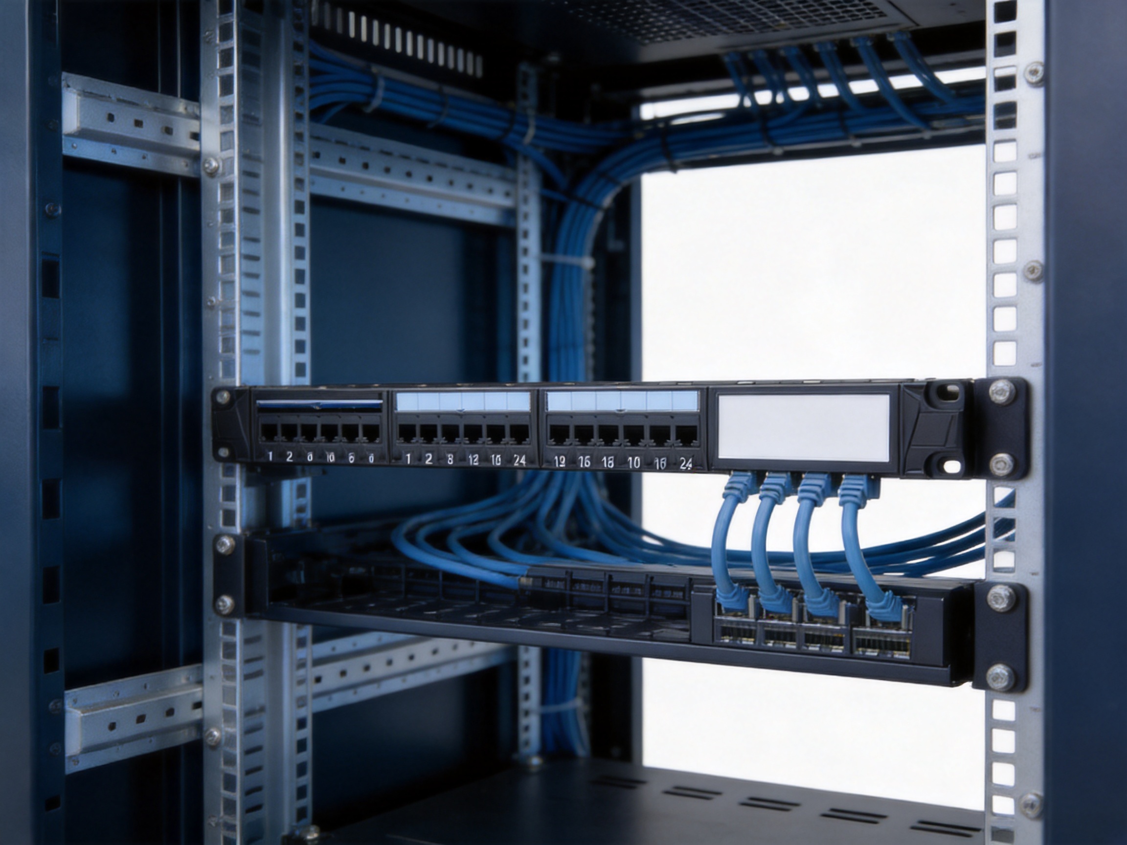
A patch panel is a passive component, but it has a direct influence on the usability and long-term reliability of a network. Instead of routing every horizontal cable directly into a switch, installers terminate permanent cables on a fixed patch panel. Short patch cords then connect the panel to switches, routers, servers, or other equipment. This arrangement creates a clear separation between permanent building cabling and equipment-side connections.
The SMT-2045D24C6 is designed for the connection of horizontal wiring and work-area wiring on the same building floor. It can also support connections involving equipment and adapters. In a typical installation, one side of the system contains permanent twisted-pair cable routed through walls, ceilings, trays, or conduits. The cable is terminated on the rear IDC terminals of the patch panel. The front RJ45 ports are then connected to network equipment by using suitable patch cords.
This approach offers several practical benefits. First, it reduces strain on switch ports because permanent cable movements are minimized. Second, it gives technicians a defined location for testing and troubleshooting. Third, it makes future changes easier because ports can be reassigned with short patch cords rather than reworking concealed building cables. Finally, the patch panel gives the rack a professional and traceable appearance.
Without a patch panel, a rack may contain a disorganized collection of cables with unclear destinations. Such an arrangement makes fault isolation more difficult and increases the possibility of accidental disconnection. A properly labeled 24-port panel provides an orderly interface between the cabling system and active equipment.
2. Product Overview and Main Configuration
The SMT-2045D24C6 is a 1U, 24-port, 180-degree CAT6 unshielded twisted-pair patch panel. The 1U height allows the product to occupy one standard rack unit, preserving valuable rack space for switches, cable management panels, power distribution units, and other equipment.
The 24-port capacity is suitable for small and medium-sized network distribution points. It can serve an office floor, a small server room, a classroom building, a retail site, a residential automation installation, or a branch communication cabinet. Multiple panels can be installed in the same rack when a larger number of network outlets is required.
| Item | Specification or Feature | Installation Benefit |
|---|---|---|
| Product type | CAT6 UTP patch panel | Supports organized copper structured cabling |
| Port quantity | 24 RJ45 ports | Provides a practical connection density for one rack unit |
| Rack format | 19-inch, 1U | Fits standard equipment racks, cabinets, and wall mounts |
| Port orientation | 180-degree design | Supports a clean and accessible termination arrangement |
| Wiring method | 110-style IDC termination | Enables dependable punch-down installation |
| Wiring sequences | T568A and T568B | Allows alignment with project wiring standards |
| Transmission range | 1 to 250 MHz | Matches the stated CAT6 operating range |
| Conductor range | 23 to 26 AWG twisted pair | Accommodates common horizontal copper cables |
| Front identification | Individual port labels and large labeling area | Improves port tracing and service work |
| Rear structure | Integrated cable manager | Guides cables toward the correct termination point |
| Environmental compliance | RoHS compliant | Supports environmentally responsible project requirements |
The combination of 24 front RJ45 ports and rear IDC terminals allows the panel to function as a fixed distribution point. The permanent cables remain connected at the back, while front patch cords can be changed as network requirements evolve.
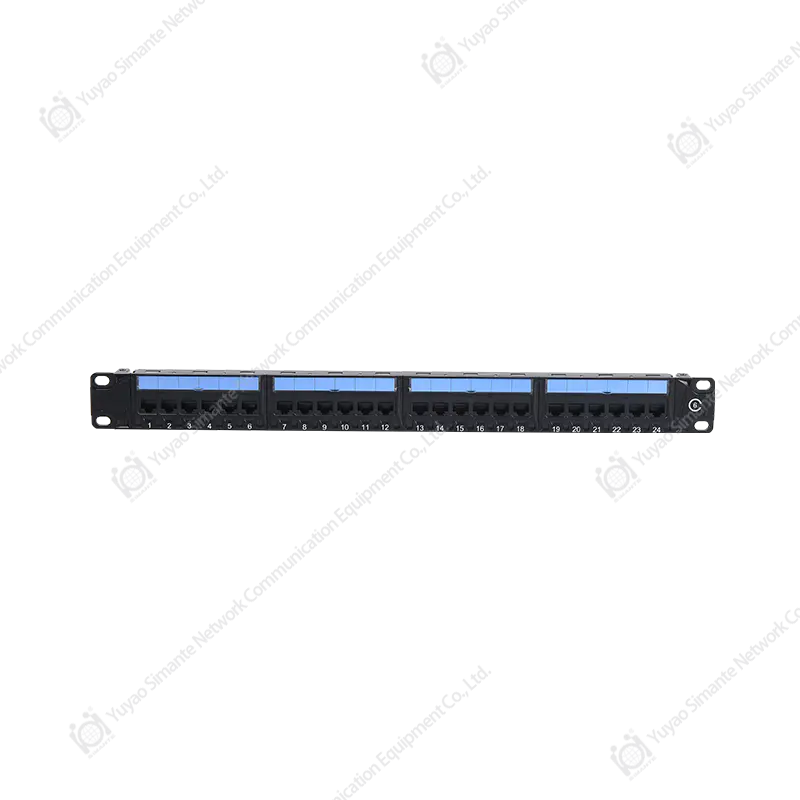
SMT-2045D24C6 1U24 Port 180 Degree CAT6 UTP Patch Panel
3. CAT6 Transmission Design
CAT6 cabling is widely used for Ethernet and other high-frequency communication applications. Compared with lower-category systems, CAT6 infrastructure is designed to provide improved transmission performance and better control of interference within the frequency range specified for the category. A patch panel used in such a system must maintain the electrical characteristics of the cable and connectors rather than becoming a weak point in the channel.
This product is specified for a frequency range of 1 to 250 MHz. The range covers the operating frequencies associated with common CAT6 structured cabling applications. The panel conforms to T568A and T568B line sequences, giving installers a standard method for arranging conductor pairs. Correct pair placement and careful termination are essential because untwisting the conductors too far or mixing pair positions can reduce performance.
The product also uses a contact-pin arrangement based on high-and-low dislocation technology. This design is intended to reduce near-end crosstalk by managing the spacing and interaction between adjacent contacts. Near-end crosstalk occurs when a signal traveling through one pair induces unwanted energy in a nearby pair. Excessive crosstalk may reduce signal quality, particularly at higher frequencies.
For this reason, the contact structure is more than a mechanical connection. The geometry of the contacts, the quality of the plating, the arrangement of the pairs, and the termination process all contribute to the final performance of the channel. A basic low-cost patch panel may provide a physical connection but offer less attention to contact arrangement, pair separation, labeling, or installation consistency. The SMT-2045D24C6 is designed as a more complete structured cabling component.
The stated near-end crosstalk attenuation value is at least 4 dB under the specified technical conditions. Installers should evaluate the complete channel, including cable, patch cords, connectors, and installation practices, when verifying a project against a required cabling standard. The panel is one component of the overall system, and its performance must be considered together with the other components.
4. Advantages of the 180-Degree 1U Format
The 1U form factor is one of the most important practical advantages of the product. Rack space is often limited, especially in compact telecommunications rooms and wall-mounted cabinets. A 24-port patch panel that occupies only one rack unit provides a high connection density without requiring a large amount of vertical space.
The 180-degree arrangement supports a straightforward path from the rear termination area to the front interface. This orientation can simplify cable routing and give technicians a clear working position during installation. It is particularly useful when the panel is installed above or below a network switch and the project requires an orderly front-to-back cabling pattern.
Standard 19-inch mounting compatibility expands the range of possible installations. The panel can be placed in equipment racks, network cabinets, and suitable wall-mounted frames. Its steel bracket provides the structural support needed for rack attachment, while the compact design makes it easier to plan equipment layouts.
Compared with oversized or irregularly shaped panels, the standardized 1U design makes replacement and expansion more predictable. Network designers can reserve rack positions in advance, use standard cage nuts or rack screws, and combine the panel with other 19-inch products. This interoperability is valuable for contractors who install equipment from different manufacturers within the same cabinet.
5. Front Labels and Rear Cable Management
Port identification is essential in every structured cabling installation. The product provides labels at the front of all 24 ports, together with a larger front labeling area. This allows customers and installers to assign port numbers, room names, outlet references, switch locations, or other project-specific information.
Clear labels reduce the time required to identify a connection. During a fault investigation, a technician can compare the port label with installation records rather than tracing an unmarked cable through a crowded rack. During a network expansion, the labeling area helps the installer determine which ports are already assigned and which are available.
The rear cable manager guides incoming cables toward the appropriate termination point. Cable management is not merely an aesthetic feature. A controlled bend path helps prevent excessive pulling force, sharp bends, and accidental pressure on IDC terminals. It also limits the amount of cable movement that occurs when nearby equipment is serviced.
Compared with a panel that provides only front ports and exposed rear terminations, the integrated rear guidance structure can improve installation consistency. It gives technicians a defined route for the cable bundle and helps maintain a cleaner relationship between each incoming cable and its corresponding port.
Good cable management also supports airflow and maintenance. A rack containing properly routed cables is easier to inspect, and there is less risk that a bundle will obstruct equipment ventilation or interfere with power connections. For data rooms containing many panels, this organizational advantage becomes increasingly significant.
6. IDC Termination and Installation Efficiency
The rear termination system uses a 110-style IDC connection method. Insulation displacement termination is widely used in structured cabling because it allows the copper conductors to be seated into an insulation displacement contact without requiring the installer to strip each conductor manually.
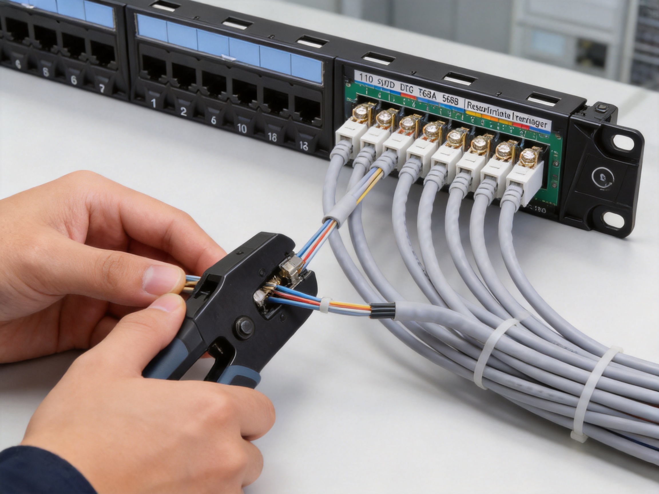
During termination, the installer places the twisted-pair conductors into the color-coded slots and uses an appropriate punch-down tool to seat them. The terminal cuts through the insulation and forms a stable electrical contact with the conductor. The process is fast, repeatable, and suitable for large installations where many cable ends must be terminated.
The color markings for the common wiring sequences make it easier to follow T568A or T568B requirements. The installer should select one sequence according to the project specification and apply it consistently across the installation. Mixing sequences without a defined reason can create wiring errors and make troubleshooting more difficult.
The IDC terminals are specified for 23 to 26 AWG twisted-pair cable. This range covers many common horizontal copper cable constructions. Before installation, the cable diameter, conductor type, and category should be checked against the project design and the complete connector system.
The design contributes to work efficiency in several ways. The 19-inch mounting format eliminates the need for custom support hardware in standard racks. The front labels reduce documentation time. The rear cable manager helps organize the cable bundle. The color-coded IDC section helps guide termination. Together, these features make the panel more practical than a basic connection board with limited installation guidance.
Professional installation remains important. The installer should avoid excessive untwisting of pairs, maintain the recommended cable bend radius, keep data cables separated from strong sources of electrical interference, and verify each port after termination. A high-quality patch panel cannot compensate for poor cable handling or incorrect wiring practices.
7. Materials and Contact Reliability
Material selection affects both the mechanical life and the electrical reliability of a patch panel. The bracket is made from cold-rolled steel with a plastic-sprayed finish. Steel provides rigidity for rack mounting, while the surface treatment helps protect the bracket and contributes to a uniform appearance.
The gold-plated contact pins are made from phosphor bronze. Phosphor bronze is commonly selected for electrical contact components because it offers a useful combination of conductivity, spring characteristics, and mechanical resilience. The specified gold-plated layer is 6 to 50U, according to the product information. The exact plating level should be confirmed for the applicable production version and project requirement.
The IDC terminal uses nickel-plated phosphor bronze. Nickel plating can support surface durability and corrosion resistance in the termination area. The non-metallic parts use PC polycarbonate and ABS materials, which are common engineering plastics for connector housings and insulating components.
The printed circuit board material is FR4. This material is widely used for rigid electrical boards because of its dimensional stability and insulating performance. In a patch panel, the board and contact assembly must maintain a consistent physical relationship during installation and repeated patching.
Compared with unreinforced plastic panels or products using less durable contact materials, the combination of steel support, phosphor bronze contacts, plated terminals, and FR4 construction provides a stronger foundation for long-term use. This is especially relevant in network rooms where ports may be accessed repeatedly and equipment may be replaced several times during the life of the building.
8. Mechanical Performance and Durability
The product information specifies an insertion force of no more than 20 N and a pull-out force of no less than 20 N for the connector interface. These values indicate that the front ports are designed to provide a controlled connection without requiring excessive force during normal patch-cord installation or removal.
The connector connection device is also specified to withstand a 50 N force for 60 ± 5 seconds. This type of mechanical requirement is relevant because cables in a rack can be pulled, shifted, or supported incorrectly during maintenance. The port structure must resist ordinary installation stresses without becoming loose or separating from the panel.
The specified durability includes 750 plug-and-socket insertion cycles and 250 wire terminations. These figures are important for environments where front patch cords are frequently changed or where a cable may need to be reterminated during commissioning and service.
Durability is one area where a professional patch panel can offer a clear advantage over very basic products. A panel intended only for occasional connection may not be suitable for a busy data room. Repeated patching can expose weak housings, poor contact springs, or low-quality plating. A product with defined mechanical and service-life requirements gives project planners a more useful basis for equipment selection.
Although the panel is built for repeated use, technicians should still handle it correctly. Patch cords should be removed by the plug body rather than by pulling the cable. Cable bundles should be supported so that their weight is not transferred directly to the ports. Punch-down terminals should not be reused beyond their rated termination count, and damaged connectors should be replaced rather than forced into service.
9. Electrical Safety and Environmental Compliance
The product has a stated working voltage of 125 V and a withstand voltage of DC 1000 V, or AC 750 V, for one minute without breakdown or arcing under the specified test conditions. These ratings describe the electrical test performance of the component and should not be interpreted as permission to use the patch panel as a power distribution device.
The insulation resistance is specified at an initial value of at least 100 MΩ and at least 100 MΩ after a constant damp-heat test. High insulation resistance helps limit unwanted leakage between conductive elements and supports reliable signal isolation.
The product is identified as meeting RoHS requirements. Restriction of hazardous substances is increasingly important for commercial construction, public procurement, international supply chains, and environmentally responsible equipment programs. RoHS compliance can simplify component selection when a project requires evidence of restricted-material control.
The stated operating temperature range is -25 to +70°C. The environmental information also specifies humidity of no more than 85 percent under the listed test condition. These values make the product suitable for many indoor telecommunications rooms and equipment cabinets when the installation environment is properly controlled.
The panel should be installed in a location protected from direct water exposure, excessive dust, chemical vapors, and condensation. While the product includes environmental and salt-spray test requirements, a standard indoor patch panel should not be treated as an outdoor or submerged component. In harsh locations, the installer should use a suitable enclosure and confirm the complete system design.
10. Salt-Spray and Corrosion Considerations
The product information defines a salt-spray test using a sodium chloride solution with a concentration of 5 ± 0.1 percent by mass. The pH range before atomization is 6.5 to 7.2 at 35 ± 2°C, and continuous atomization is recommended for 48 hours. These details provide a defined method for evaluating resistance to a corrosive salt-laden environment.
Salt-spray testing is useful for assessing surface treatments and plated metal components. It can reveal weaknesses in coatings, exposed edges, contact surfaces, and structural parts. Although a telecommunications room is normally not exposed to salt spray, this type of testing provides additional information about the robustness of the product materials.
The test also specifies the use of chemically pure or analytically pure sodium chloride and distilled or deionized water. Oil, dust, and impurities must be controlled because they can affect the test result. Such requirements show the importance of repeatable manufacturing and verification procedures.
For coastal buildings, marine facilities, industrial plants, and areas with elevated atmospheric contamination, the installer should assess the complete environment rather than relying only on the patch panel rating. Rack cabinets, cable glands, grounding arrangements, and other hardware must also be suitable for the location.
11. Manufacturing Strength and Quality Control
The manufacturer, Yuyao Simante Network Communication Equipment Co., Ltd., integrates product design, development, sales, and service. Its experience in network cabling and optical fiber products supports a product development approach centered on structured cabling applications rather than isolated connector production.
The company reports nearly 20 years of service in the network communication field. This operating history is relevant because passive cabling components must remain compatible with changing network architectures, installation practices, and customer requirements. Experience across multiple product generations can help a manufacturer identify common installation problems and improve connector design.
The company has more than 10 engineers and over 30 full-time technical personnel. This technical structure supports product development, process engineering, quality control, production support, and customer-specific projects. A dedicated engineering team is particularly valuable for OEM and ODM work, where a customer may require changes in labeling, packaging, materials, port configurations, or mechanical dimensions.
The reported manufacturing base includes 10 regular and customization production lines, 10 fully automatic injection molding machines, 20 semi-automatic injection molding machines, and eight automatic installation machines. This combination of automated and semi-automated equipment provides flexibility. Automated machinery can support repeatability and production volume, while semi-automatic processes can be useful for customized variants and special configurations.
The factory reports an annual output of more than 9 million units. A production capacity of this scale can support consistent supply for distributors, system integrators, construction contractors, and international projects. It also indicates that the company has experience coordinating material procurement, assembly, inspection, packaging, and export logistics at commercial volume.
Manufacturing capacity alone does not guarantee quality, so process control remains important. For a product such as this patch panel, relevant control points include plastic injection dimensions, contact assembly alignment, plating quality, IDC terminal positioning, labeling accuracy, rack bracket geometry, port insertion performance, and final packaging inspection.
The product’s defined electrical, mechanical, durability, environmental, and corrosion-related requirements provide a framework for inspection. This is an advantage over products sold with only a basic port count and category label, because documented technical parameters give buyers more information for comparing products and preparing project specifications.
12. Competitive Advantages in Practical Installations
The SMT-2045D24C6 competes most effectively where installers need more than a low-cost set of RJ45 openings. Its principal advantage is the combination of structured installation features in a standard 1U chassis.
First, the 24-port density makes efficient use of rack space. A project can provide a substantial number of copper connections without sacrificing several rack units. This is valuable in small cabinets and in high-density distribution frames.
Second, the front labeling system supports better documentation and service. A panel with visible identification is easier to operate than one where technicians must depend on handwritten cable tags or undocumented port assignments.
Third, the rear cable manager creates a more controlled termination environment. This can improve appearance, reduce cable stress, and make future maintenance easier.
Fourth, the 110-style IDC method and T568A/T568B markings support familiar installation practices. Contractors do not need to adopt an unusual termination method or develop special procedures for the panel.
Fifth, the materials and test specifications support long-term use. Steel mounting hardware, phosphor bronze contacts, plated surfaces, FR4 construction, insertion-cycle testing, and wire-termination testing are meaningful differentiators when compared with generic products that provide little technical detail.
Sixth, the product is suitable for both standard and customized supply programs. The manufacturer’s reported production lines, engineering personnel, and OEM/ODM experience can be useful for customers that require specific packaging, markings, labels, or project configurations.
Finally, the product is part of a broader structured cabling portfolio that includes keystone jacks, wall faceplates, data sockets, and related network communication components. Purchasing compatible components from an experienced manufacturer can help reduce variation across a project and simplify technical coordination.
13. Recommended Installation Workflow
13.1 Prepare the Rack Position
Confirm that the rack or cabinet follows the 19-inch standard and that one clear rack unit is available. Check the required mounting screws, cage nuts, grounding provisions, cable paths, and equipment spacing before installing the panel.
13.2 Plan the Port Assignment
Prepare a port schedule before terminating cables. The schedule may include room number, outlet number, cable identifier, switch port, VLAN assignment, or service type. A clear plan reduces labeling changes after installation.
13.3 Select the Wiring Sequence
Choose T568A or T568B according to the project specification. The same sequence should normally be used consistently throughout the structured cabling system unless a defined crossover or special connection is required.
13.4 Route the Permanent Cables
Bring the horizontal cables to the rear of the panel through the intended rack pathway. Maintain the cable manufacturer’s bend-radius requirements and avoid sharp turns, crushing, excessive tension, and unnecessary untwisting of the pairs.
13.5 Terminate the IDC Contacts
Place each conductor in the correct color-coded IDC slot. Use a suitable punch-down tool and ensure that the conductors are fully seated. Remove excess conductor ends where appropriate and confirm that the cable jacket is supported close to the termination area.
13.6 Apply Identification
Mark the front port labels and the larger identification area according to the project documentation. Labels should be durable, legible, and consistent with the numbering system used for wall outlets, cable records, and switch ports.
13.7 Test Each Link
Use an appropriate cable tester to verify wire map, continuity, pair integrity, length, and other required parameters. If the project requires certification, test the complete permanent link or channel according to the applicable testing procedure.
13.8 Connect Patch Cords
After testing, connect the front ports to network equipment using suitable patch cords. Route the cords through horizontal or vertical cable managers to reduce tension and maintain clear airflow in the cabinet.
14. Applications
The panel is suitable for office network distribution points where multiple work-area outlets must be connected to switches. Its 24-port capacity can support a department, small floor, branch office, or service area.
It can also be used in educational facilities. Classrooms, laboratories, administrative offices, and access-control systems often require organized copper connections that can be documented and modified over time.
Retail and hospitality environments can use the panel for point-of-sale systems, wireless access points, IP cameras, telephones, digital signage, and building management devices. A labeled termination point simplifies maintenance when services are added or relocated.
Residential structured wiring cabinets and smart-home installations can benefit from the compact form factor. The 1U format allows the panel to be installed with network switches, routers, security gateways, and automation equipment in a small enclosure.
Industrial offices and light manufacturing facilities may also use the panel in protected indoor cabinets. Where the environment contains severe dust, vibration, moisture, or corrosive chemicals, the complete enclosure and installation method should be evaluated carefully.
System integrators can use the product as part of a broader copper and fiber structured cabling solution. Copper patch panels can be installed alongside fiber distribution products, rack accessories, wall outlets, and modular jacks to create a consistent infrastructure across a site.
15. Packaging, Storage, and Logistics
The product is placed in a dedicated blister bag and then packed in a carton with its accessories. The carton is identified with the product model and quantity. This packaging approach helps protect the panel from dust, handling damage, and surface abrasion during transportation and storage.
The stated storage environment is an indoor warehouse with an ambient temperature of -5 to +30°C and relative humidity not exceeding 70 percent. The surrounding air should be free from acid, alkali, and other corrosive gases. Under the stated conditions, the storage period is three years.
Proper storage matters because connector components can be affected by moisture, chemical exposure, impact, and contamination before installation. Cartons should remain sealed until the product is ready for use. They should not be stored directly on damp floors or in locations exposed to condensation.
The regular packing quantity is stated as 10 boxes per carton, with one product per box and 10 products per carton. Customers requiring private labeling, customer-specified packaging, or special accessory arrangements can discuss those requirements with the manufacturer as part of an OEM or project supply program.
16. Specification Selection Guidance
When selecting a patch panel, buyers should first confirm the cable category and conductor size. This product is intended for CAT6 UTP structured cabling and supports 23 to 26 AWG twisted-pair cable. If a project uses shielded cable, a different shielded panel may be required.
The rack dimensions and port quantity should then be checked. A 1U, 24-port panel is appropriate when the rack layout requires a compact distribution point. Projects with a higher port count may use multiple panels, while smaller installations may select a lower-density configuration.
Buyers should also review the required wiring standard, labeling method, test requirements, operating environment, and regulatory documentation. A patch panel should be selected as part of a complete channel design rather than treated as an isolated component.
For international projects, customers may require product drawings, material declarations, quality inspection records, packing specifications, sample approvals, or custom labels. The manufacturer’s reported engineering and customization capabilities can support this type of project coordination.
17. Maintenance Recommendations
Routine maintenance begins with visual inspection. Technicians should check that the panel remains securely mounted, labels are legible, patch cords are not sharply bent, and cable bundles are properly supported.
Unused ports should be protected from dust and accidental damage when the environment requires it. Patch cords should be replaced if their latches, plugs, or strain reliefs are damaged. A loose connection should not be corrected by repeatedly forcing the plug into the port.
Documentation should be updated whenever a port is reassigned. The front label, rack schedule, cable database, and switch configuration should remain consistent. Accurate records are particularly important in facilities with frequent tenant changes, network upgrades, or shared equipment rooms.
When troubleshooting, technicians should begin with the physical layer. Check the patch cord, front port, rear termination, cable route, and remote outlet before replacing active equipment. A structured patch panel makes this process easier because the permanent cable termination and equipment connection are visibly separated.
18. Frequently Asked Questions
What is the purpose of the SMT-2045D24C6?
It provides a fixed termination and distribution point for CAT6 unshielded twisted-pair cabling. Permanent horizontal cables terminate at the rear IDC contacts, while front RJ45 ports connect to switches and other network equipment through patch cords.
How many ports does the panel provide?
The panel provides 24 RJ45 ports in a 1U rack-mounted format.
Does it fit a standard 19-inch rack?
Yes. It is designed for standard 19-inch equipment racks, cabinets, and suitable wall-mounted frames.
What wiring standards does it support?
The panel supports both T568A and T568B line sequences. The selected sequence should match the project specification and be applied consistently throughout the installation.
What termination method is used?
The rear connection uses a 110-style IDC termination method. The IDC section is specified for 23 to 26 AWG twisted-pair cable.
Is the panel shielded?
The product is specified as a CAT6 UTP patch panel, meaning it is intended for unshielded twisted-pair systems. Projects using shielded cabling should select a compatible shielded solution.
What is the operating frequency range?
The stated frequency range is 1 to 250 MHz.
Why are the front labels important?
Front labels allow technicians to identify ports by room, outlet, cable number, or service. They reduce tracing time and support accurate documentation during installation and maintenance.
What is the purpose of the rear cable manager?
The rear cable manager guides incoming cables toward the correct IDC termination points. It helps control cable routing, reduce mechanical stress, and maintain a cleaner rack installation.
How durable are the ports?
The product information specifies 750 plug-and-socket insertion cycles and 250 wire terminations. These figures indicate suitability for repeated service and maintenance when the product is installed and handled correctly.
What materials are used?
The bracket uses cold-rolled steel with a plastic-sprayed finish. The contact pins use gold-plated phosphor bronze, the IDC terminals use nickel-plated phosphor bronze, the plastic parts use PC and ABS, and the circuit board uses FR4 material.
Is the product suitable for outdoor installation?
It is primarily intended for indoor racks, cabinets, and protected telecommunications spaces. Outdoor or severe industrial installations require a suitable enclosure and an evaluation of temperature, moisture, dust, chemical exposure, and corrosion conditions.
Can the product be customized?
The manufacturer reports regular and customization production lines and undertakes OEM and ODM projects. Customers can discuss labeling, packaging, product configuration, and other project requirements before ordering.
How should the panel be tested after installation?
Each link should be checked with a suitable copper cable tester for continuity, wire map, pair integrity, and other project-specific parameters. Certification testing should follow the applicable cabling standard and the requirements of the system owner.
19. Conclusion
The SMT-2045D24C6 1U 24-Port 180 Degree CAT6 UTP Patch Panel is designed to provide a practical, organized, and durable interface for copper structured cabling systems. Its 24-port 1U format makes efficient use of rack space, while the 19-inch mounting design supports installation in standard racks, cabinets, and wall-mounted frames.
Its key advantages include CAT6-oriented electrical design, T568A and T568B support, 110-style IDC termination, visible front labeling, rear cable management, a high-and-low dislocation contact arrangement, and defined mechanical and environmental performance. The steel bracket, plated phosphor bronze contacts, FR4 board, PC and ABS components, and specified durability testing provide a stronger technical foundation than a basic unverified patch panel.
The product is also supported by a manufacturer with reported experience in network cabling and optical fiber products, dedicated engineering and technical personnel, automated and semi-automated production resources, customization capabilities, and international supply experience. These strengths are valuable for distributors, installers, system integrators, and project owners seeking consistent structured cabling components.
When installed with suitable CAT6 cable, compliant patch cords, correct termination practices, proper labeling, and complete link testing, the panel can help create a more manageable and serviceable network infrastructure. It is therefore a practical choice for commercial, educational, residential, retail, hospitality, and protected industrial communication applications.
References
1. YD/T 926.1-2009, General Specification for Integrated Wiring System.
2. YD/T 926.3-2009, Sub-Standard for Integrated Wiring System Components.
3. ANSI/TIA-568 Series, Telecommunications Cabling and Balanced Twisted-Pair Cabling Requirements.
4. ISO/IEC 11801 Series, Information Technology—Generic Cabling for Customer Premises.
5. RoHS Directive Requirements for the Restriction of Hazardous Substances in Electrical and Electronic Equipment.
6. Product technical information for the SMT-2045D24C6 1U 24-Port 180 Degree CAT6 UTP Patch Panel.
7. Manufacturer-provided information regarding materials, production capacity, packaging, storage, and environmental testing.