

 Español
 عربى
عربى русский
Content
- 1 Product Positioning in a Structured Cabling System
- 2 Core Design: 2U, 48 Ports, 180-Degree Termination
- 3 Category 6 Transmission Capability
- 4 Compatibility with T568A and T568B Wiring Sequences
- 5 IDC Termination Compatible with 110 and Krone Methods
- 6 Front Labeling for Better Network Management
- 7 Rear Cable Management and Strain Reduction
- 8 Mechanical Strength and Rack Compatibility
- 9 Electrical and Mechanical Specification Overview
- 10 Material Selection and Long-Term Reliability
- 11 Insertion Force, Pull-Out Force, and Connection Stability
- 12 Environmental Resistance and Storage Stability
- 13 Advantages Compared with Ordinary Patch Panels
- 14 Manufacturing Strength Behind the Product
- 15 Advanced Injection Molding and Dimensional Control
- 16 Automatic Installation and Assembly Consistency
- 17 Quality Control from Design Source to Final Shipment
- 18 Application Scenarios
- 19 Installation Best Practices
- 20 Why This Patch Panel Creates Value for Distributors and Project Contractors
- 21 Integration with Copper and Fiber Structured Cabling Solutions
- 22 Customization and OEM/ODM Support
- 23 Q&A Section
- 23.1 What is the main use of this 2U 48-port Cat6 UTP patch panel?
- 23.2 Why is the 2U 48-port design useful?
- 23.3 Does the panel support both T568A and T568B wiring?
- 23.4 What conductor sizes can be terminated on the IDC blocks?
- 23.5 What makes this product different from ordinary low-cost patch panels?
- 23.6 Can it be installed in standard racks and cabinets?
- 23.7 Why is rear cable management important?
- 23.8 What kind of durability does the RJ45 interface provide?
- 23.9 Is the product environmentally compliant?
- 23.10 What manufacturing strengths support product reliability?
- 24 Conclusion
- 25 References
- 26 Product: SMT-2032D48C6-B 2U48 Port 180 Degree CAT6 UTP Patch Panel
In modern copper cabling infrastructure, the patch panel is far more than a passive mounting accessory. It is the organized center of horizontal cabling, equipment connections, port identification, channel reliability, and future maintenance. The 2U 48-port 180-degree Cat6 UTP patch panel is designed for structured cabling projects that require high density, stable Category 6 performance, efficient installation, and long-term operational clarity in equipment rooms, network cabinets, data distribution points, commercial buildings, campuses, smart facilities, and enterprise communication networks.
This product is a 19-inch rack-mount, 48-port, Category 6 unshielded twisted pair patch panel with 180-degree IDC termination. It is built to support Category 6 transmission requirements across a frequency range of 1 to 250 MHz, and it is compatible with T568A and T568B wiring sequences. It provides the central cross-connection point between vertical backbone distribution and horizontal work-area cabling, allowing installers, contractors, integrators, and end users to manage copper network links with clear labeling, reliable mechanical structure, and efficient termination.
The value of this patch panel lies in the combination of electrical performance, mechanical durability, installation efficiency, and manufacturing consistency. In competitive cabling markets, many patch panels may appear similar from the front view, but differences in contact design, IDC quality, plastic molding, metal frame treatment, printed circuit board material, labeling area, rear cable management, testing discipline, and production control can have a direct effect on signal reliability and field service life. This 2U 48-port Cat6 patch panel is engineered to solve those practical problems.
SMT-2032D48C6-B 2U48 Port 180 Degree CAT6 UTP Patch Panel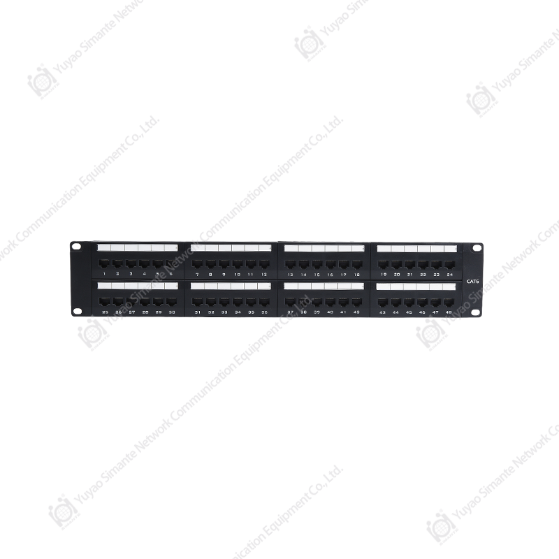
Product Positioning in a Structured Cabling System
A structured cabling system depends on predictable and repeatable connections. Cables, keystone jacks, patch cords, face plates, distribution frames, and patch panels must work together under a common standard. The 2U 48-port Cat6 UTP patch panel is mainly used to connect horizontal cabling to equipment-side jumpers in the same floor or telecommunications room. It allows the fixed cabling inside a building to remain stable while active equipment such as switches, routers, or network appliances can be changed, maintained, or expanded through patch cords.
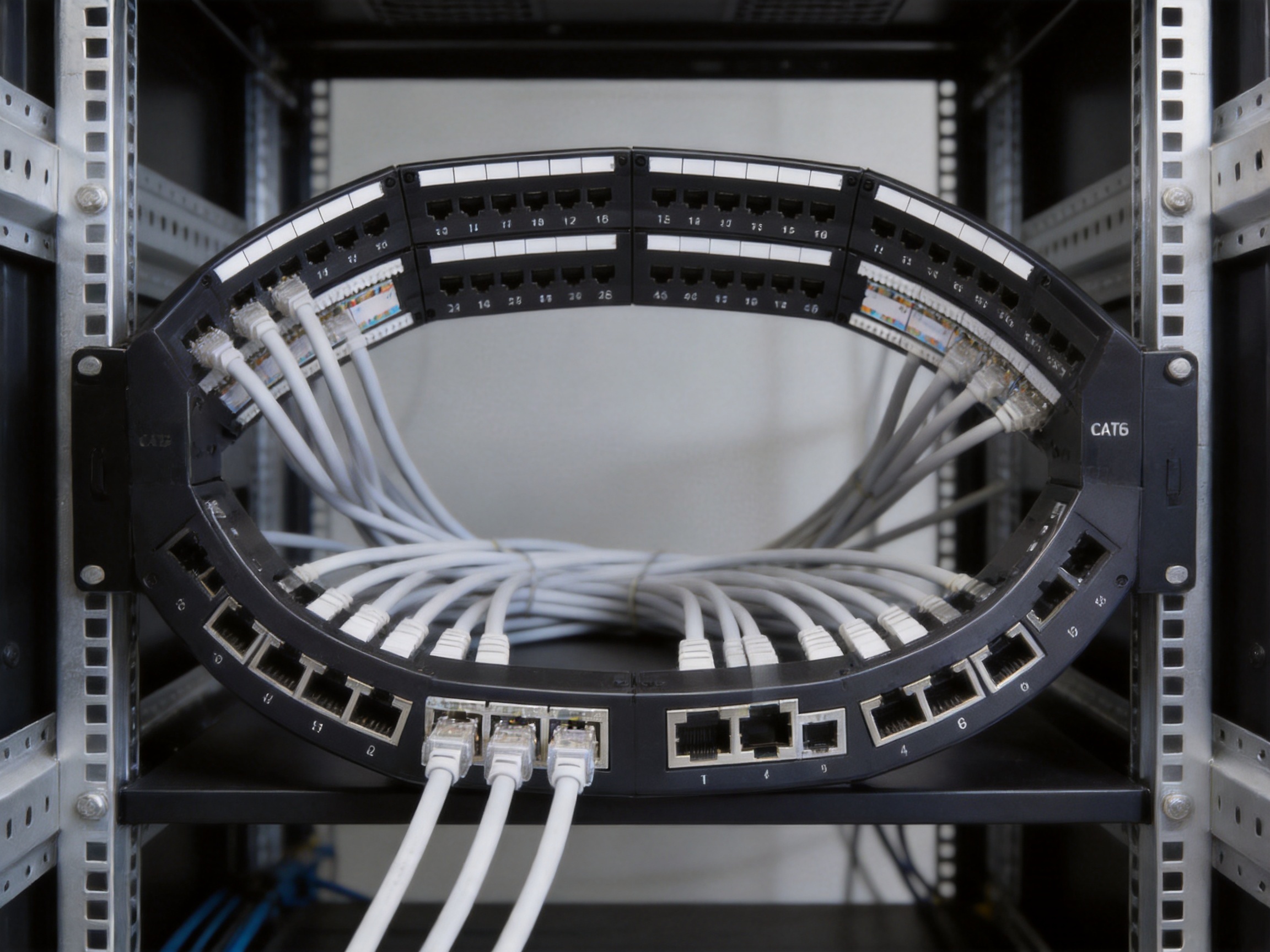
In a typical installation, horizontal cables from work areas are terminated at the rear IDC blocks of the patch panel. The front RJ45 ports are then connected to network switches or other equipment using Cat6 patch cords. This architecture protects permanent links from frequent movement and gives administrators a clean, labeled, and standardized interface for moves, adds, and changes.
The 48-port capacity in a 2U format is especially suitable for medium- and high-density installations. It provides a strong balance between port density and accessibility. Compared with lower-density solutions, it can save rack space and reduce the number of separate panels required for a project. Compared with ultra-high-density compact systems, the 2U format gives installers more working room, clearer port identification, and easier rear cable routing. This makes it practical for commercial buildings, schools, hospitals, hotels, factories, data rooms, and smart building projects where reliability and maintainability matter as much as initial installation speed.
Core Design: 2U, 48 Ports, 180-Degree Termination
The patch panel follows the standard 19-inch rack-mount form factor and is compatible with standard equipment racks, network cabinets, and wall-mounted rack systems. The 2U height provides room for 48 RJ45 ports arranged for easy front access. Each port has front labeling space, helping technicians identify circuit numbers, user locations, equipment functions, VLAN groups, department assignments, or other site-specific designations.
The 180-degree termination design means that the rear cable termination path aligns in a straight, organized direction. This can be advantageous in cabinets where cables are routed from above or below and need to be dressed neatly to the rear termination area. The rear cable manager supports cable guidance toward the IDC termination points, reducing strain on the terminated conductors and improving the visual and mechanical order of the installation.
The front RJ45 jack connects to patch cords, while the rear IDC accepts horizontal wiring. This separation between front patching and rear permanent cable termination is one of the main reasons patch panels are preferred in professional cabling. It prevents repeated handling of permanent cables and gives operators a safer, faster way to modify network assignments.
Category 6 Transmission Capability
Category 6 cabling is designed to support higher bandwidth and better crosstalk performance than Category 5e systems. The product is specified for a frequency range from 1 to 250 MHz, aligning it with the common performance class expected for Cat6 installations. In practical networks, this supports stable data transmission for many enterprise applications, including Gigabit Ethernet and other structured cabling uses within the limits of applicable standards and channel designs.
One of the critical challenges in copper connectivity is near-end crosstalk. Crosstalk occurs when signals in one pair interfere with signals in another pair. In dense panels with many adjacent ports, careful contact arrangement and PCB design become important. This patch panel uses a contact pin design based on high and low dislocation technology, which helps reduce near-end crosstalk values. This is a meaningful advantage over low-cost panels that may rely only on simplified RJ45 structures without sufficient pair separation or controlled contact geometry.
For project owners, Cat6 performance is not only about speed claims. It is about repeatability from port to port. A panel with stable Category 6 construction can help reduce troubleshooting time, improve certification pass rates, and support consistent long-term service. When combined with proper Cat6 horizontal cable, compatible connectors, qualified patch cords, and correct installation practices, this panel becomes an important part of a reliable copper channel.
Compatibility with T568A and T568B Wiring Sequences
The patch panel conforms to both T568A and T568B wiring sequences. This gives installers flexibility because different projects, regions, and existing facilities may use different wiring conventions. The universal color label on the panel supports accurate and fast termination, reducing the risk of pair reversal, split pairs, or inconsistent wiring between ports.
Field termination errors remain one of the common causes of structured cabling faults. A clear color-coded label is a small design detail with major practical importance. It helps installers work faster while still maintaining correct pair order. It is also useful during inspection and future maintenance because technicians can verify wiring logic visually without unnecessary guesswork.
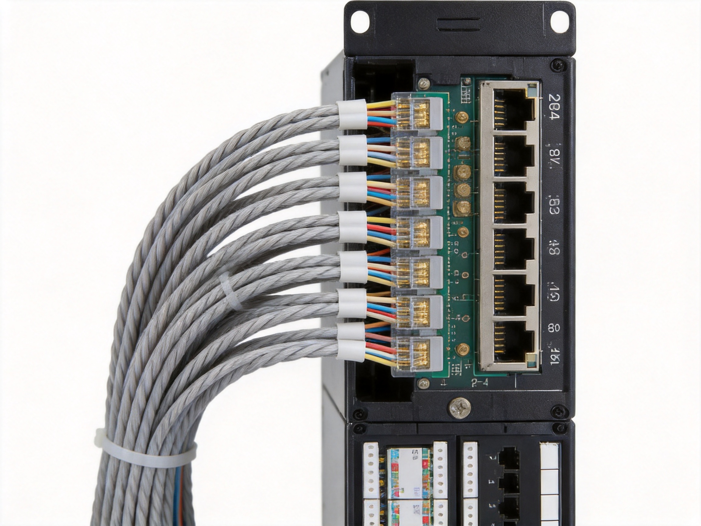
IDC Termination Compatible with 110 and Krone Methods
The rear IDC wiring structure is compatible with 110-type and Krone-style termination methods. This gives installers broader tooling flexibility and makes the panel easier to integrate into different project workflows. In many regions, technicians already have established habits and tools for one IDC method or the other. A panel that can accommodate both approaches can reduce training difficulty and improve installation efficiency.
The IDC terminals are designed to clamp 23 to 26 AWG twisted-pair conductors. This conductor range is practical for common Cat6 UTP cable types used in horizontal cabling. Proper IDC contact pressure is essential because too little force can cause intermittent connections, while excessive deformation can damage conductors. The use of phosphor bronze nickel-plated IDC terminals helps provide mechanical elasticity, corrosion resistance, and consistent electrical contact.
Front Labeling for Better Network Management
Each of the 48 ports includes front labeling space, and the panel provides a large label area for customer port identification. This improves daily operation after the installation is complete. Network cabinets often become difficult to manage when port labels are unclear, missing, or too small. In contrast, a panel with visible identification areas supports faster troubleshooting, easier documentation, and safer network changes.
Good labeling reduces service interruption risk. When a technician needs to disconnect or repatch a cable, the ability to identify the correct port quickly can prevent accidental downtime. This is especially important in offices, hotels, schools, and production environments where network service continuity is important. The large label format also supports customized numbering systems required by consultants, contractors, or end-user IT departments.
Rear Cable Management and Strain Reduction
A professional patch panel must protect the cable termination area. The rear cable manager on this product guides incoming cables to the IDC positions and helps reduce mechanical stress on the connection points. Cable management is not simply about appearance. It affects bend radius, tension control, airflow, accessibility, and the long-term stability of terminations.
In many low-grade installations, cables are left hanging from the rear of the panel, placing continuous tension on IDC blocks. Over time, this can create poor contact, conductor movement, or hard-to-locate intermittent faults. A rear management structure gives the installer a place to organize cable bundles, route conductors properly, and maintain consistent service loops. This is a practical advantage for long-term maintenance and for projects subject to inspection.
Mechanical Strength and Rack Compatibility
The bracket is made of cold-rolled steel with plastic spraying surface treatment. Cold-rolled steel provides rigidity and dimensional stability, while the sprayed surface helps protect against wear and corrosion. In equipment rooms, patch panels may be subject to repeated patching, cable movement, rack vibration, and handling during installation. A strong metal frame helps keep port alignment stable and supports clean rack mounting.
The 19-inch rack standard is important because it makes the panel compatible with common cabinets, open racks, and wall-mounted frames. This compatibility reduces project complexity. Integrators do not need special mounting accessories for most standard installations, and the product can be used in new projects or upgrades of existing racks.
The 2U height also gives the product a sturdy front presence. For 48 ports, 2U can be easier to handle than highly compressed formats because technicians have more room for fingers, labels, patch cord insertion, and port inspection. This improves work efficiency, particularly in sites where technicians may need to make frequent changes.
Electrical and Mechanical Specification Overview
The following table summarizes key technical characteristics and practical meanings of the 2U 48-port Cat6 UTP patch panel.
| Specification Area | Product Detail | Practical Benefit |
|---|---|---|
| Mounting Format | 19-inch rack mount, 2U height | Compatible with standard racks, cabinets, and wall-mount frames |
| Port Capacity | 48 RJ45 ports | High-density copper network organization in one panel |
| Category | Category 6 UTP | Supports Cat6 structured cabling requirements |
| Frequency Range | 1 to 250 MHz | Suitable for Cat6 transmission applications |
| Wiring Sequence | T568A and T568B | Flexible installation in different cabling environments |
| Termination | IDC for horizontal wiring, RJ45 for patch cords | Separates permanent cabling from equipment patching |
| IDC Compatibility | 110-type and Krone-style methods | Supports common field termination tools and practices |
| Conductor Range | 23 to 26 AWG twisted pair | Compatible with common Cat6 cable sizes |
| Working Voltage | 125 V | Meets specified operating electrical requirement |
| Withstand Voltage | DC 1000 V or AC 750 V for 1 minute without breakdown or arcing | Provides insulation and safety verification under test conditions |
| Insulation Resistance | Initial value at least 100 MΩ; after damp heat test at least 100 MΩ | Supports stable insulation performance in controlled tests |
| Insertion Durability | Plug and socket insertion rated for 750 cycles | Suitable for repeated patching in network rooms |
| Wire Termination Durability | IDC termination rated for 250 cycles | Supports maintenance and retermination requirements |
| Environmental Requirement | RoHS compliant | Supports environmental responsibility and project compliance |
| Operating Temperature | -25 to +70 degrees Celsius | Suitable for varied indoor equipment-room conditions |
Material Selection and Long-Term Reliability
The product uses a combination of metallic and non-metallic materials selected for conductivity, elasticity, insulation, durability, and manufacturing stability. The gold needle contacts are made from phosphor bronze with gold plating. Phosphor bronze is widely used in connector contacts because it combines good spring properties with electrical conductivity and fatigue resistance. Gold plating improves contact reliability by reducing oxidation at the mating surface.
The specified gold-plated layer range is 6 to 50 microinches. Different project or customer requirements may require different plating thicknesses, but the availability of this range reflects the manufacturer’s ability to support varied market demands. Higher-quality contact plating can be especially valuable in environments where patch cords are inserted and removed repeatedly.
The IDC card wire terminals are made from phosphor bronze with nickel plating. Nickel plating contributes to surface protection and contact durability. For IDC terminations, the terminal must cut through cable insulation and maintain stable contact with the copper conductor. The spring behavior of phosphor bronze helps maintain contact pressure over time.
The plastic components use PC polycarbonate and ABS materials. PC is known for toughness, dimensional stability, and heat resistance, while ABS offers processability and mechanical strength. Proper plastic selection is important because modular jack housings, separators, and insulation bodies must hold contact geometry accurately. Small dimensional variation can affect insertion force, retention, and electrical performance.
The PCB uses FR4 material, a common flame-resistant glass-reinforced epoxy laminate used in electronic interconnection products. In a patch panel, the PCB helps manage signal paths and pair relationships. Consistent PCB material and controlled manufacturing are important for Cat6 crosstalk performance and port-to-port consistency.
Insertion Force, Pull-Out Force, and Connection Stability
The specified insertion force is not more than 20 N, and the pull-out force is not less than 20 N. These mechanical values matter because RJ45 connections must be easy enough for technicians to operate but firm enough to avoid accidental disconnection. Excessive insertion force can make patching difficult and may indicate poor contact alignment. Insufficient pull-out retention can lead to loose patch cords and unstable links.
The connector connection device is specified to withstand 50 N for 60 ± 5 seconds. This test condition helps verify mechanical robustness. In real installations, patch cords may be pulled, moved, bundled, or repositioned. A stable port structure reduces the risk of physical damage during routine maintenance.
The plug and socket insertion durability of 750 cycles supports repeated patching. This is important in network rooms where ports may be reconfigured over the lifetime of the building. While permanent links should remain stable, front patching often changes as offices move, devices are upgraded, network segmentation changes, or equipment is replaced.
Environmental Resistance and Storage Stability
The patch panel is specified for operation from -25 to +70 degrees Celsius, with humidity up to 85 percent under the stated temperature condition. These values indicate suitability for many indoor telecommunications spaces and equipment rooms. Although professional cabling products should still be installed in controlled environments whenever possible, environmental tolerance helps protect performance in real-world conditions.
The product also includes salt spray test requirements. Salt spray testing is used to evaluate corrosion resistance of metallic parts under accelerated conditions. The described test uses a sodium chloride solution with controlled concentration and pH, continuous atomization, and a recommended duration of 48 hours. This type of evaluation is particularly relevant for metal frames, contacts, and plated components because corrosion can affect mechanical integrity and electrical contact reliability.
RoHS compliance reflects attention to environmental and material restrictions. For contractors serving international projects, RoHS status can be an important procurement consideration. It supports responsible manufacturing and helps customers meet regulatory or internal environmental requirements.
Advantages Compared with Ordinary Patch Panels
The competitive advantage of this patch panel begins with its balanced design. Many basic panels can provide RJ45 ports, but not all of them combine high-density 48-port capacity, 2U accessibility, universal wiring labels, 110 and Krone IDC compatibility, rear cable management, cold-rolled steel structure, Cat6 frequency support, and durable plated contacts in one product.
First, the 2U 48-port layout offers a practical density-to-accessibility ratio. Some lower-cost panels may reduce space but make labeling and cable management difficult. Others may provide easy access but consume more rack units. This product gives enough space for identification and handling while still supporting 48 ports in a compact rack footprint.
Second, the high and low dislocation contact design helps reduce near-end crosstalk. In Cat6 cabling, internal contact arrangement is not a cosmetic feature; it directly affects performance. Panels with less refined contact geometry may create avoidable signal coupling, resulting in failed certification tests or unstable high-speed links.
Third, the front label area and rear cable manager address long-term operational needs. A product that is easy to install but difficult to maintain can increase lifetime cost. Clear labeling and guided cable routing reduce troubleshooting time, support neat cabinets, and help maintain the quality of the installation after handover.
Fourth, material choices such as phosphor bronze contacts, gold plating, nickel-plated IDC terminals, FR4 PCB, PC, ABS, and sprayed cold-rolled steel contribute to long service life. Some competitor products may use thinner metal, lower-grade plastics, inconsistent plating, or simplified PCB structures to reduce cost. Such shortcuts may not be visible at first glance, but they can appear later as port looseness, failed terminations, poor contact, or inconsistent testing results.
Fifth, compatibility with both T568A and T568B and with 110 and Krone termination practices improves field flexibility. Contractors benefit from fewer tooling restrictions and reduced training barriers. This can make installation faster and reduce mistakes, particularly across large projects with multiple installation teams.
Manufacturing Strength Behind the Product
A reliable patch panel depends not only on design but also on manufacturing discipline. Yuyao Simante Network Communication Equipment Co., Ltd. is a professional manufacturer of network cabling solutions and optical fiber products integrating design, development, sales, and service. With nearly 20 years of industry service, the company has developed experience in structured cabling components, network communication accessories, smart home network infrastructure, automation equipment cabling, and related products.
The company’s product range includes keystone jacks, patch panels, wall face plates, data sockets, and other structured cabling components. This broad product coverage is important because a patch panel does not work alone. It must connect with jacks, patch cords, cables, cabinets, and terminal outlets. A manufacturer familiar with the full cabling ecosystem can design products with better interoperability and practical installation details.
The company has more than 10 engineers and over 30 full-time technical personnel. This technical team supports product development, process improvement, quality control, testing, and customization. Engineering depth is valuable in copper connectivity because small changes in contact geometry, plastic dimensions, plating, IDC structure, or PCB layout can influence transmission performance and mechanical durability.
The factory is equipped with 10 regular and customized production lines, 10 fully automatic injection molding machines, 20 semi-automatic injection molding machines, and 8 sets of automatic installation machines. These manufacturing resources support stable production capacity and consistency. The reported annual output of more than 9 million units indicates the scale needed to serve both standard and customized project requirements.
Advanced Injection Molding and Dimensional Control
For a Cat6 patch panel, plastic components must be accurate, repeatable, and strong. RJ45 modules, insulating housings, wire guides, clips, and internal supports all require dimensional precision. If molding tolerances are inconsistent, contacts may shift, plug insertion may feel uneven, and electrical performance may vary from port to port.
The use of fully automatic and semi-automatic injection molding machines allows the manufacturer to control production efficiency while supporting different part types and project quantities. Automatic molding improves consistency for high-volume parts, while semi-automatic capacity can support customized production or specialized components. This combination helps the factory balance mass production and flexible customer requirements.
Good injection molding also supports appearance quality. A patch panel installed in a professional cabinet should have a clean, consistent front face, stable port positioning, and durable plastic parts. However, the deeper value of molding quality is internal: it holds contact geometry and IDC alignment in the right position. This directly supports termination reliability and Cat6 performance.
Automatic Installation and Assembly Consistency
Automatic installation machines help improve assembly stability. Patch panel production involves multiple repetitive processes, including contact placement, IDC assembly, module fitting, PCB positioning, housing assembly, and inspection. Manual assembly alone can be effective for small quantities, but high-volume production requires process control to reduce variation.
Automatic assembly equipment improves repeatability, reduces human error, and supports stable output. For customers, this means different batches of the same product are more likely to perform consistently. In structured cabling projects, consistency matters because panels may be installed across multiple floors, buildings, or phases. A consistent product reduces installation surprises and supports standardized documentation.
The company’s production capabilities also support OEM and ODM projects. This is important for distributors, system integrators, and brand owners who need customized packaging, labeling, plating requirements, port numbering, or product combinations. Customization is more reliable when backed by engineering and production resources rather than only trading capability.
Quality Control from Design Source to Final Shipment
The company emphasizes quality stability from the design source. This approach is important because testing finished products alone cannot fully compensate for weak design. A strong patch panel begins with correct material selection, contact layout, PCB design, port spacing, IDC geometry, and mechanical structure. When these are controlled at the design stage, mass production becomes more stable.
Quality management also includes performance testing. The manufacturer supports customer testing requirements and maintains attention to product quality for high-end markets. For a Cat6 patch panel, relevant testing may include electrical continuity, insulation resistance, withstand voltage, insertion and extraction force, IDC termination reliability, crosstalk performance, mechanical fit, visual inspection, and packaging verification.
Packaging is also part of quality protection. The product is placed into a special blister bag and then into a cardboard box, with accessories included and labels indicating product model and quantity. Proper packaging protects ports, labels, metal surfaces, and IDC components during transportation and storage. Regular packing quantity is 10 boxes per carton, with 1 product per box and 10 products per carton.
The packaged products should be stored in a warehouse with ambient temperature from -5 to +30 degrees Celsius, relative humidity not more than 70 percent, and no acid, alkali, or other corrosive gases in the surrounding air. The stated storage period is three years under suitable conditions. These storage guidelines help distributors and project contractors maintain product condition before installation.
Application Scenarios
The 2U 48-port Cat6 UTP patch panel is suitable for a wide range of structured cabling projects. In office buildings, it can organize user network outlets by department, floor, or functional area. In schools and universities, it can manage classroom, laboratory, library, and administration network points. In hotels, it can support guest room data ports, access points, IPTV connections, back-office systems, and service networks. In hospitals and clinics, it can help organize communication points for administrative systems, monitoring devices, workstations, and medical support areas where structured cabling discipline is essential.
In industrial and automation environments, the panel can be used in control rooms or communication cabinets where copper Ethernet connections must be organized and labeled. In smart homes and smart buildings, it can provide the distribution point for data sockets, wireless access points, security systems, and automation controllers. In small data rooms and enterprise network cabinets, the panel can connect user access switches to horizontal cabling while keeping the rack neat and serviceable.
The product is also useful for system upgrades. Many buildings still contain older cabling layouts with poor documentation or scattered terminations. Replacing disorganized terminations with a clear 48-port Cat6 patch panel can improve management immediately. When used with qualified cable testing and proper labeling, it can help bring the cabling environment closer to professional structured cabling standards.
Installation Best Practices
To obtain the best performance from the patch panel, installers should follow recognized structured cabling practices. The cable jacket should be stripped carefully without damaging conductor insulation. Twisted pairs should remain twisted as close as possible to the IDC termination point. Excessive untwisting can degrade crosstalk performance, especially in Category 6 systems.
The installer should choose either T568A or T568B consistently across the project unless a specific design requires otherwise. Mixing wiring schemes without documentation can create confusing faults. The color label on the panel should be followed carefully, and each conductor should be fully seated in the IDC terminal using the appropriate punch-down tool.
Cables should be routed through the rear cable manager with appropriate bend radius and strain relief. They should not be pulled tightly against the IDC blocks. Bundle ties should not crush the cable jacket, because deformation of twisted pairs can affect transmission performance. Hook-and-loop cable ties are often preferable for maintaining cable geometry.
After termination, every link should be tested with suitable certification or verification equipment according to the project requirement. Testing should include wire map, length, continuity, and performance parameters appropriate for Cat6 channels or permanent links. Clear front labeling should be completed immediately after testing so that documentation and physical ports match.
Why This Patch Panel Creates Value for Distributors and Project Contractors
For distributors, a patch panel must be reliable, easy to sell, and suitable for repeat orders. This product offers clear commercial advantages: standard 19-inch compatibility, strong Cat6 positioning, 48-port density, practical 2U design, recognizable material specifications, RoHS compliance, and packaging suitable for inventory management. Because it addresses common installer needs, it can serve a broad market rather than a narrow specialty segment.
For project contractors, installation efficiency directly affects labor cost and project schedule. The universal color label, 110 and Krone compatibility, rear cable manager, and clear front identification area reduce installation friction. Contractors can complete terminations faster, reduce mistakes, and present a cleaner final cabinet to clients. The result is not only a functional network but also a professional-looking installation that supports customer confidence.
For end users, the value appears during the years after installation. Clear labels, durable ports, stable contacts, and organized cables make network changes less risky. A well-built patch panel can reduce downtime, simplify troubleshooting, and extend the usable life of the cabling infrastructure. In many organizations, the cost of network interruption is far greater than the cost difference between a low-grade panel and a professionally manufactured one.
Integration with Copper and Fiber Structured Cabling Solutions
Although this product belongs to the copper system as a Cat6 patch panel, it can be part of a broader network cabling solution that includes fiber products. Modern buildings often use fiber backbone links between telecommunications rooms, data rooms, or buildings, while copper cabling serves work-area outlets and local devices. A manufacturer with both copper and fiber system experience can better support complete structured cabling projects.
In a typical design, optical fiber may carry high-capacity backbone traffic, while Cat6 copper cabling distributes network connectivity to desks, access points, cameras, phones, and controllers. The patch panel serves as the organized copper endpoint in that architecture. When copper and fiber components are sourced from a manufacturer with integrated product knowledge, customers can benefit from more consistent supply, coordinated technical support, and simplified procurement.
Customization and OEM/ODM Support
Project requirements vary by region, customer brand, packaging standard, and technical preference. The manufacturer’s ability to undertake OEM and ODM projects is an important advantage. Customization can include packaging, labels, model identification, accessory configuration, gold-plating options, and project-specific presentation. This flexibility helps distributors and system integrators build differentiated offerings without sacrificing manufacturing reliability.
Customization should not mean unstable quality. Because the factory has established production lines, injection molding capacity, automatic assembly equipment, and technical personnel, it can support customized work with process discipline. This is especially valuable for customers in Europe, Australia, Africa, the Middle East, and Southeast Asia, where market requirements, certifications, languages, and project formats may differ.

Q&A Section
What is the main use of this 2U 48-port Cat6 UTP patch panel?
It is used as the central termination and management point for horizontal copper cabling in structured cabling systems. Rear IDC blocks connect to permanent horizontal cables, while front RJ45 ports connect to equipment through patch cords.
Why is the 2U 48-port design useful?
The 2U design provides high port density while preserving enough space for labeling, patch cord access, and cable management. It is a practical choice for installations that require many copper connections without making the cabinet difficult to maintain.
Does the panel support both T568A and T568B wiring?
Yes. The panel supports both T568A and T568B wiring sequences and includes universal color labeling to help installers terminate conductors accurately and quickly.
What conductor sizes can be terminated on the IDC blocks?
The IDC terminals are suitable for 23 to 26 AWG twisted-pair conductors, which are commonly used in Category 6 UTP horizontal cabling.
What makes this product different from ordinary low-cost patch panels?
Key differences include the 2U 48-port layout, front labeling area, rear cable manager, Cat6 frequency support, high and low dislocation contact design for crosstalk reduction, phosphor bronze contacts, gold-plated mating surfaces, nickel-plated IDC terminals, FR4 PCB material, and a cold-rolled steel sprayed bracket.
Can it be installed in standard racks and cabinets?
Yes. It is designed for 19-inch rack mounting and is compatible with common equipment racks, network cabinets, and wall-mounted rack frames.
Why is rear cable management important?
Rear cable management guides cables toward the termination points, reduces strain on IDC contacts, helps maintain proper bend radius, and makes the cabinet easier to inspect and maintain over time.
What kind of durability does the RJ45 interface provide?
The plug and socket insertion durability is specified at 750 cycles, making it suitable for routine patching and network reconfiguration over the product’s service life.
Is the product environmentally compliant?
The product is specified to meet RoHS requirements, supporting environmental compliance for professional cabling projects.
What manufacturing strengths support product reliability?
The manufacturer has engineering personnel, technical teams, multiple regular and customized production lines, fully automatic and semi-automatic injection molding machines, automatic installation machines, and experience in copper and fiber structured cabling products. These resources support stable quality, customization, and large-scale supply.
Conclusion
The 2U 48-port 180-degree Cat6 UTP patch panel is a practical and reliable component for professional copper structured cabling systems. It combines high-density port capacity, standard 19-inch rack compatibility, Category 6 transmission support, T568A and T568B wiring flexibility, 110 and Krone IDC compatibility, clear front labeling, rear cable management, and durable material construction.
Its advantages are not limited to technical specifications. The product is designed around real installation and maintenance needs: faster termination, fewer wiring errors, cleaner cabinets, stronger cable support, clearer documentation, and more stable long-term operation. Compared with ordinary patch panels that focus only on basic connectivity, this model offers a more complete balance of performance, usability, durability, and manufacturing consistency.
Behind the product is a manufacturer with nearly two decades of experience in network cabling solutions and optical fiber products, supported by engineering teams, technical personnel, injection molding capacity, automatic assembly equipment, testing awareness, and OEM/ODM service capability. For distributors, contractors, and end users seeking dependable structured cabling components, this patch panel provides a strong solution for modern copper network infrastructure.
References
ANSI/TIA-568, Commercial Building Telecommunications Cabling Standard.
ISO/IEC 11801, Information Technology: Generic Cabling for Customer Premises.
YD/T 926.1-2009, General Specification for Telecommunications Cabling Systems.
YD/T 926.3-2009, Telecommunications Cabling System Sub-Standard for Connecting Hardware.
IEC 60603-7 Series, Connectors for Electronic Equipment: Detail Specification for 8-Way Connectors.
RoHS Directive, Restriction of Hazardous Substances in Electrical and Electronic Equipment.


